Spacing tool

a tool and tool body technology, applied in the field of hand tools, can solve the problems of difficult removal for users by simply grasping and pulling, and the inability to easily remov

Inactive Publication Date: 2008-01-17
BINGHAM JOHN FREDERICK
View PDF10 Cites 7 Cited by
  • Summary
  • Abstract
  • Description
  • Claims
  • Application Information

AI Technical Summary

Problems solved by technology

A common shortcoming of such devices is the inability to easily remove them when compressive forces between the two boards applied to the device squeeze the device with a level of force that makes it difficult for a user to remove by simply grasping and pulling.

Method used


Image

  • Spacing tool
  • Spacing tool
  • Spacing tool

Examples


Embodiment Construction

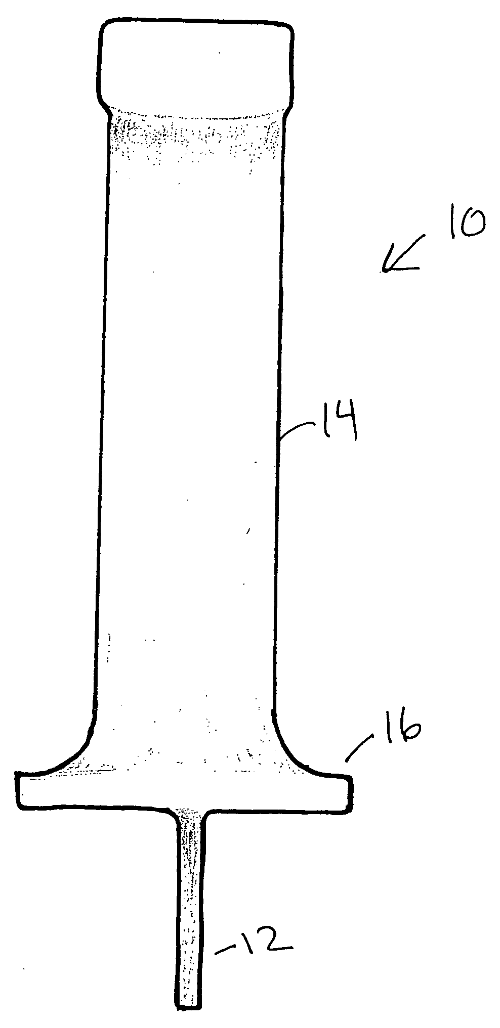
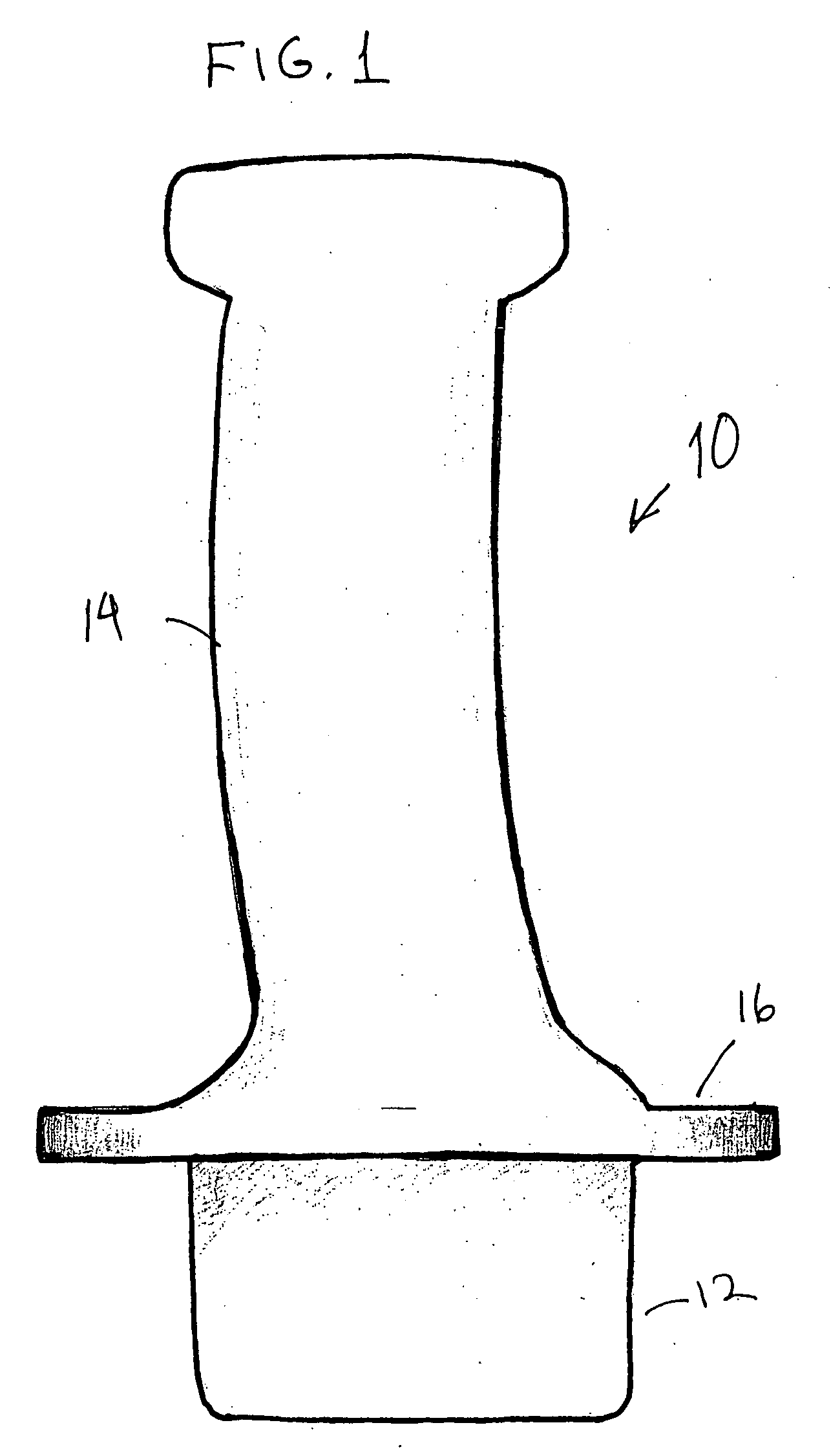
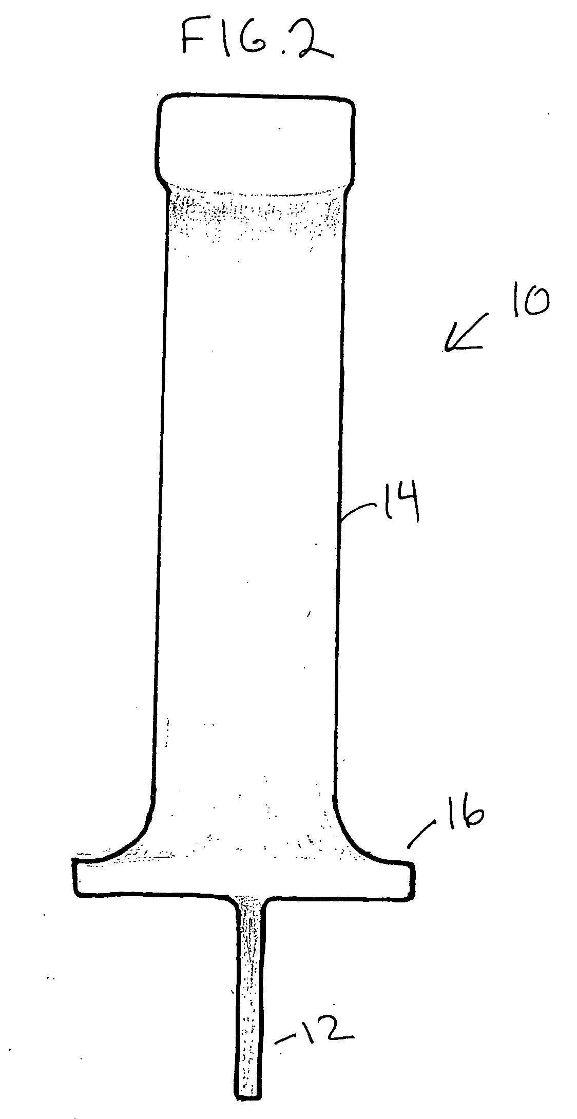
[0010]A hand tool according to the present invention is described herein with respect to FIGS. 1-3. A tool (10) includes a generally planar body (12) attached to a handle (14) having a flange (16) positioned at the end of the handle (14) closest to the planar body (12). The tool (10) may be of uniform construction or of multiple, assembled parts. The tool (10) may be made of high impact plastic, metal, wood, other known materials, or a combination thereof. It may be molded or machined.

[0011]The blade (12) has a thickness that is approximately equal to a desired, predetermined spacing that will be used between two objects to be assembled to a third object such as, for example, to deck boards being fastened to a substructure. The present invention is not limited to deck board construction and it has many potential uses. For illustrative purposes, the description herein will refer to deck boards as an example. The blade (12) should be of sufficient length to extend vertically between t...


PUM


Abstract

A hand tool (10) includes a generally planar body (12) having a thickness approximately equal to a predetermined desired spacing between two objects such as deck boards, a flange (16) having a contact surface generally perpendicular to the planar body, and a handle (14) extending from the flange in a direction away from the planar body. In use, the planar body is inserted between two boards while one or both boards are fastened to a substructure. The tool is removed by grasping the handle and either pulling it out or rocking it so that a portion of the flange acts like a fulcrum to pivot the planar body out of the space between the two boards.

Description

RELATED APPLICATIONS[0001]This application claims priority from U.S. Provisional Application 60 / 698,373, which was filed on Jul. 12, 2005.TECHNICAL FIELD[0002]The present invention relates to hand tools and, more particularly, to hand tools used for assisting a technician in maintaining alignment of two objects while one or both are fastened to a third object such as, for example, deck boards.BACKGROUND OF THE INVENTION[0003]Various building and repair procedures require assembly of two objects to a third object wherein the first two objects require predetermined spacing and alignment. For example, in building a deck or platform consisting of elongated boards or sections fastened to a substructure, it is necessary to align the boards in parallel with equal spacing.[0004]Known hand tools to assist in such procedures include generally flat objects that are positioned between the boards, sometimes at spaced intervals, to maintain the spacing and alignment. A common shortcoming of such ...

Claims


Application Information

Patent Timeline
Patent Type & Authority Applications(United States)
IPC IPC(8): G01D21/00
CPCE04F21/0092
Inventor BINGHAM, JOHN FREDERICK
Owner BINGHAM JOHN FREDERICK
Why Eureka
Try Eureka