Remotely operable door lock interface system

a door lock and remote operation technology, applied in the field of remote operation of door lock interface systems, can solve the problems of not offering the protection needed for some consumers, occupying hands, and inability to quickly and efficiently unlock the door, and achieve the effect of instructing the electric motor

Inactive Publication Date: 2008-01-17
GROFF JOHN K
View PDF15 Cites 42 Cited by
  • Summary
  • Abstract
  • Description
  • Claims
  • Application Information

AI Technical Summary

Benefits of technology

[0014]An elongated and rectilinear rod is statically conjoined directly to the stop member and extends horizontally inwardly away from a jam side of the door. Such a rod has a serrated distal end oppositely facing the bolt, wherein the serrated distal end faces downwardly. A drive gear has a toothed outer surface interlocked with the serrated distal end such that the rod linearly travels along the horizontal path when the drive gear rotates clockwise and counterclockwise respectively. An electric motor and a drive shaft are directly conjoined thereto. Such a drive shaft is directly coupled to the drive gear and is responsive to the stationary and portable controllers respectively for effectively causing the drive gear to rotate in the clockwise and counter clockwise directions.
[0016]A coded input signal is generated and transmitted by the portable controller based upon a user input. A coded output signal is generated and transmitted by the stationary controller based upon instructions received from the coded input signal. Such a coded output signal is wirelessly transmitted to the internal controller for conveniently and effectively instructing the electric motor to rotate in the clockwise and counter clockwise directions during operating conditions.
[0018]A security panel is directly affixed to one side of the door. Such a panel covers one of the door cavities and effectively prohibits unauthorized access thereto. The security panel is provided with a plurality of coextensively shaped annular openings for advantageously allowing a door handle and a deadbolt housing to be operably connected directly to the door while conveniently maintaining the automatic extending and retracting mechanism hidden from the environment.

Problems solved by technology

Over the years, incidents relating to home burglaries and theft have steadily increased.
Though these devices are known to work successfully, they may not offer the protection needed for some consumers.
This causes their hands to be occupied and unavailable to quickly and efficiently unlock the door, which is a typical, yet potentially dangerous, scenario.
The horizontal displacement can be obtrusive and bulky, thereby producing a product, which is not aesthetically pleasing, something undesirable by many consumers.
In addition, the design and configuration of the connecting rod to the conventional dead bolt and actuator is such that after extended use, it may dislodge therefrom.
Further still, this system is solely utilized for dead bolts and does not address other locking systems typically used in a home, office or the like.

Method used


Image

  • Remotely operable door lock interface system
  • Remotely operable door lock interface system
  • Remotely operable door lock interface system

Examples


Embodiment Construction

[0041]The present invention will now be described more fully hereinafter with reference to the accompanying drawings, in which a preferred embodiment of the invention is shown. This invention may, however, be embodied in many different forms and should not be construed as limited to the embodiment set forth herein. Rather, this embodiment is provided so that this application will be thorough and complete, and will fully convey the true scope of the invention to those skilled in the art. Like numbers refer to like elements throughout the figures.

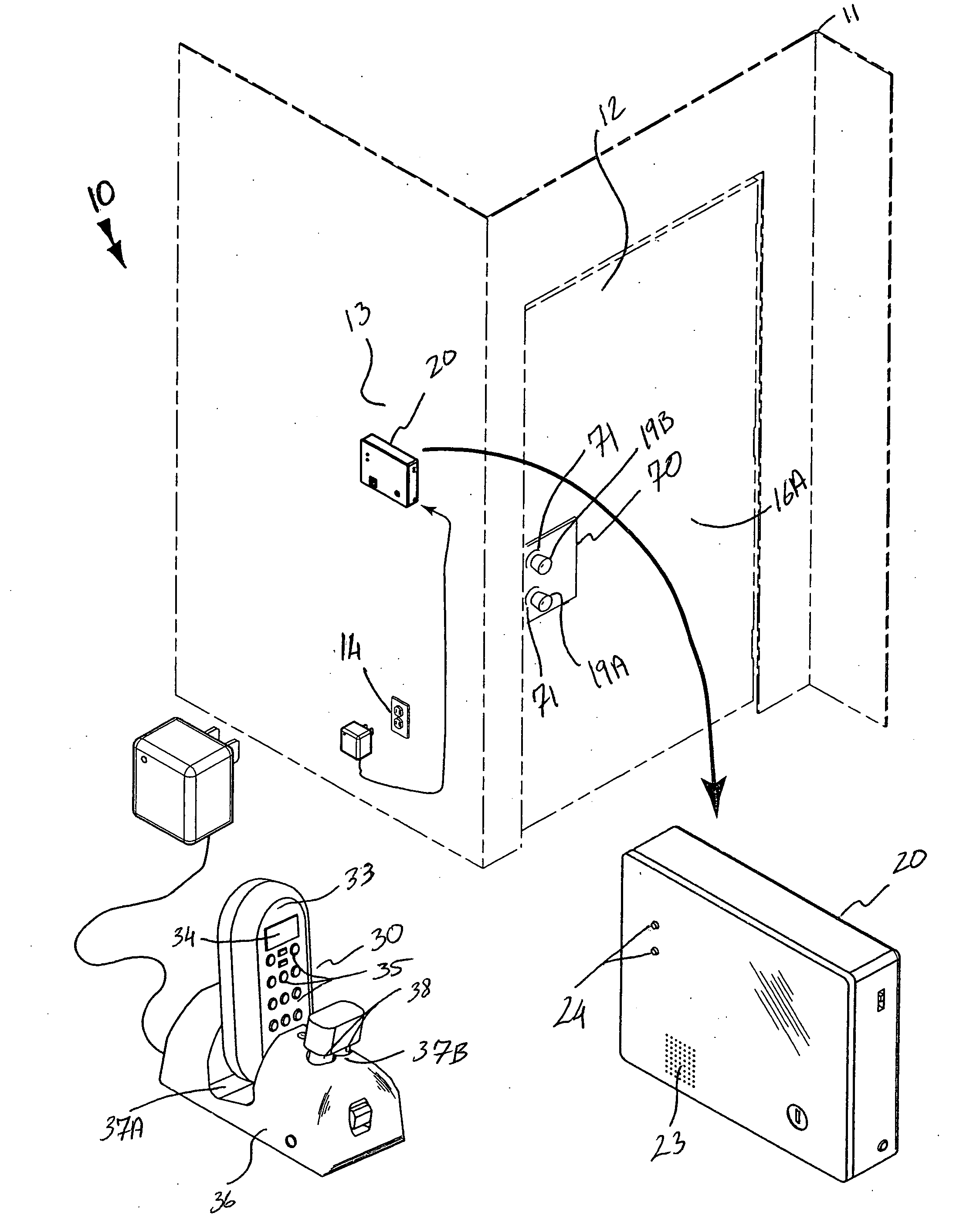
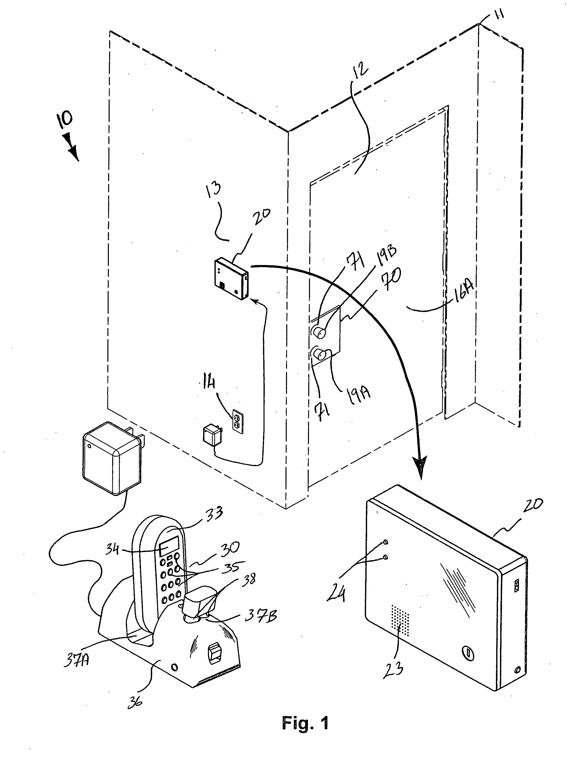
[0042]The system of this invention is referred to generally in FIGS. 1-19 by the reference numeral 10 and is intended to provide a remotely operable door lock interface system. It should be understood that the system 10 may be used to remotely operate many different types of locks and should not be limited in use to only deadbolt door locks.

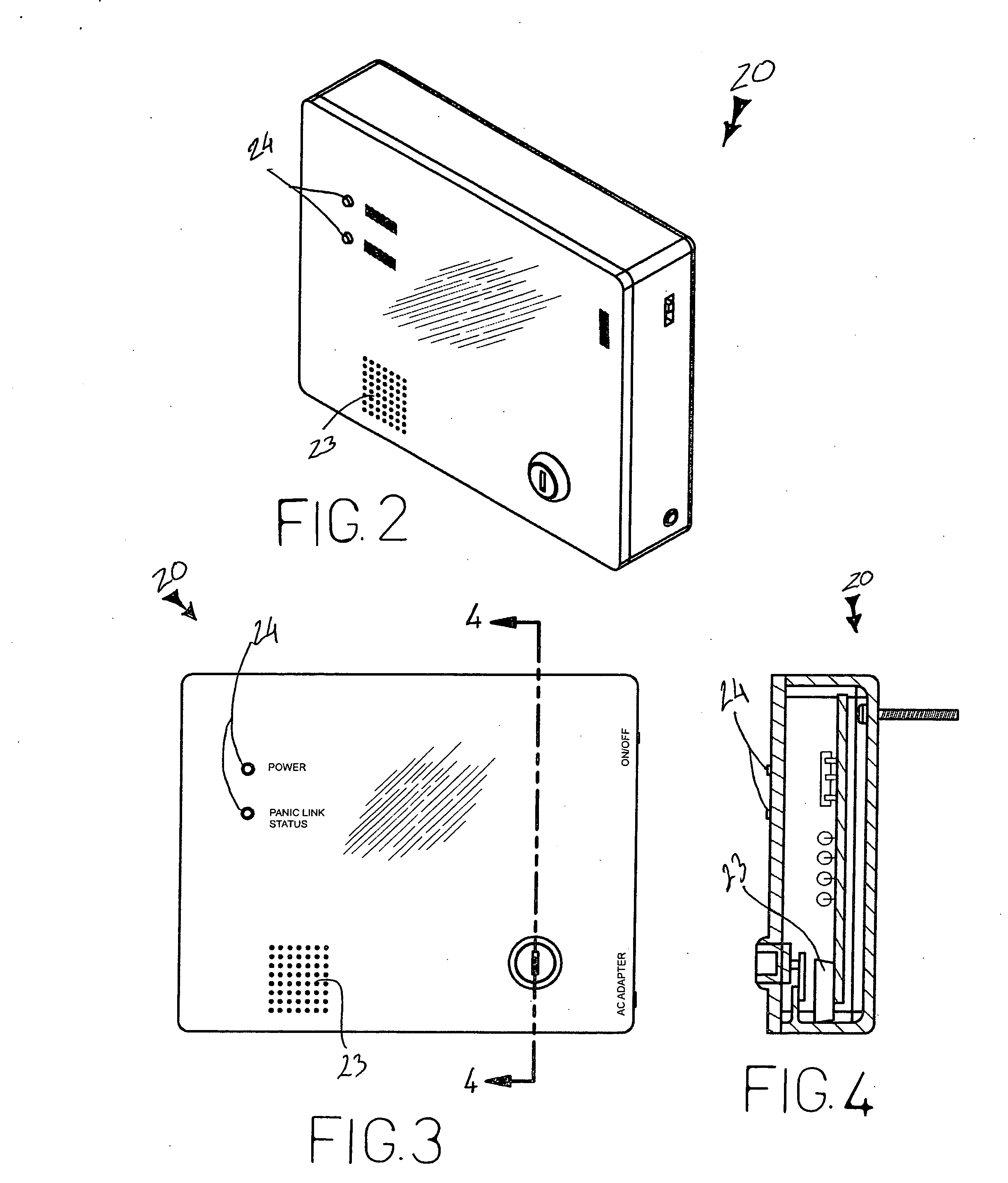
[0043]Referring initially to FIGS. 1, 2, 3, 4 and 19, the system 10 includes a stationary controller 20...


PUM


Abstract

A door lock interface system includes a stationary controller that is mounted to a support surface at an interior of a building. A portable controller is in wireless communication with the stationary controller. An elongated and rectilinear bolt is positioned through a slot of a door and is spaced from the stationary and portable controllers. A mechanism is included for automatically retracting and extending the bolt along a parallel and horizontal path. A mechanism is included for bypassing the automatic retracting and extending mechanism such that the user can manually retract and extend the bolt. A security panel is affixed to one side of the door and covers one door cavity, prohibiting unauthorized access thereto. The security panel is provided with annular openings, allowing a door handle and a deadbolt housing to be connected to the door while maintaining the automatic extending and retracting mechanism hidden from the environment.

Description

CROSS REFERENCE TO RELATED APPLICATIONS[0001]Not Applicable.STATEMENT REGARDING FEDERALLY SPONSORED RESEARCH OR DEVELOPMENT[0002]Not Applicable.REFERENCE TO A MICROFICHE APPENDIX[0003]Not Applicable.BACKGROUND OF THE INVENTION[0004]1. Technical Field[0005]This invention relates to remotely operable locking systems and, more particularly, to a remotely operable door lock interface system.[0006]2. Prior Art[0007]Over the years, incidents relating to home burglaries and theft have steadily increased. This increase has concerned the consumer and these concerns have lead them to invest in more elaborate home safety devices, including the use of dead bolts, burglar alarms, a combination thereof, or the like. Though these devices are known to work successfully, they may not offer the protection needed for some consumers. For example, some consumers do not have their keys ready for insertion into the lock and many find themselves searching through their belongings in hopes of finding their ...

Claims


Application Information

Patent Timeline
Patent Type & Authority Applications(United States)
IPC IPC(8): E05B65/12B60R25/04
CPCE05B9/00E05B47/0012E05B47/026G07C2009/00793E05B2047/0016E05B2047/002E05B63/0069Y10T70/5199Y10T70/5314Y10T70/5978
Inventor GROFF, JOHN K.
Owner GROFF JOHN K
Why Eureka
Try Eureka