Shooting structure of a paint bullet gun

a paint bullet gun and shooting structure technology, applied in the direction of compressed gas guns, white arms/cold weapons, weapons, etc., can solve the problems of gas waste, inapplicability to handgun length, and the b>62/b> gunlock cannot be easily moved smoothly, so as to increase the number of shot paint bullets

Inactive Publication Date: 2008-01-17
LAI BAO SHYAN
View PDF16 Cites 25 Cited by
  • Summary
  • Abstract
  • Description
  • Claims
  • Application Information

AI Technical Summary

Benefits of technology

[0006]It is therefore a primary object of the present invention to provide a shooting structure of a paint bullet gun. In the paint bullet gun, the gas reservoir communicates with the internal space of the tubular member via the flow ways. Therefore, the gas entering the gas reservoir also serves to drive the gunlock. Accordingly, one single gas supply is used to control movement of the gunlock as well as the shooting of the paint bullet. Therefore, it is no more necessary to add another gas supply for driving the gunlock. In addition, when the gunlock is moved forward, the gas is fed back to the gas reservoir. Therefore, the gas can be recovered and reused to increase the number of the shot paint bullets.
[0007]It is a further object of the present invention to provide the above shooting structure of the paint bullet gun. The guide stem of the controlling member extends into the gunlock, whereby the gunlock can axially move along the guide stem to shorten the necessary axial moving space for the gunlock. Therefore, the length of the gun body can be shortened to facilitate holding of the paint bullet gun. Such length is applicable to a handgun.

Problems solved by technology

Therefore, the gas is wasted.
Therefore, such length is not applicable to a handgun.
In case of poor precision, the gunlock 62 can be hardly smoothly moved.
As a result, the paint bullet gun will malfunction and cannot be further used.

Method used


Image

  • Shooting structure of a paint bullet gun
  • Shooting structure of a paint bullet gun
  • Shooting structure of a paint bullet gun

Examples


Embodiment Construction

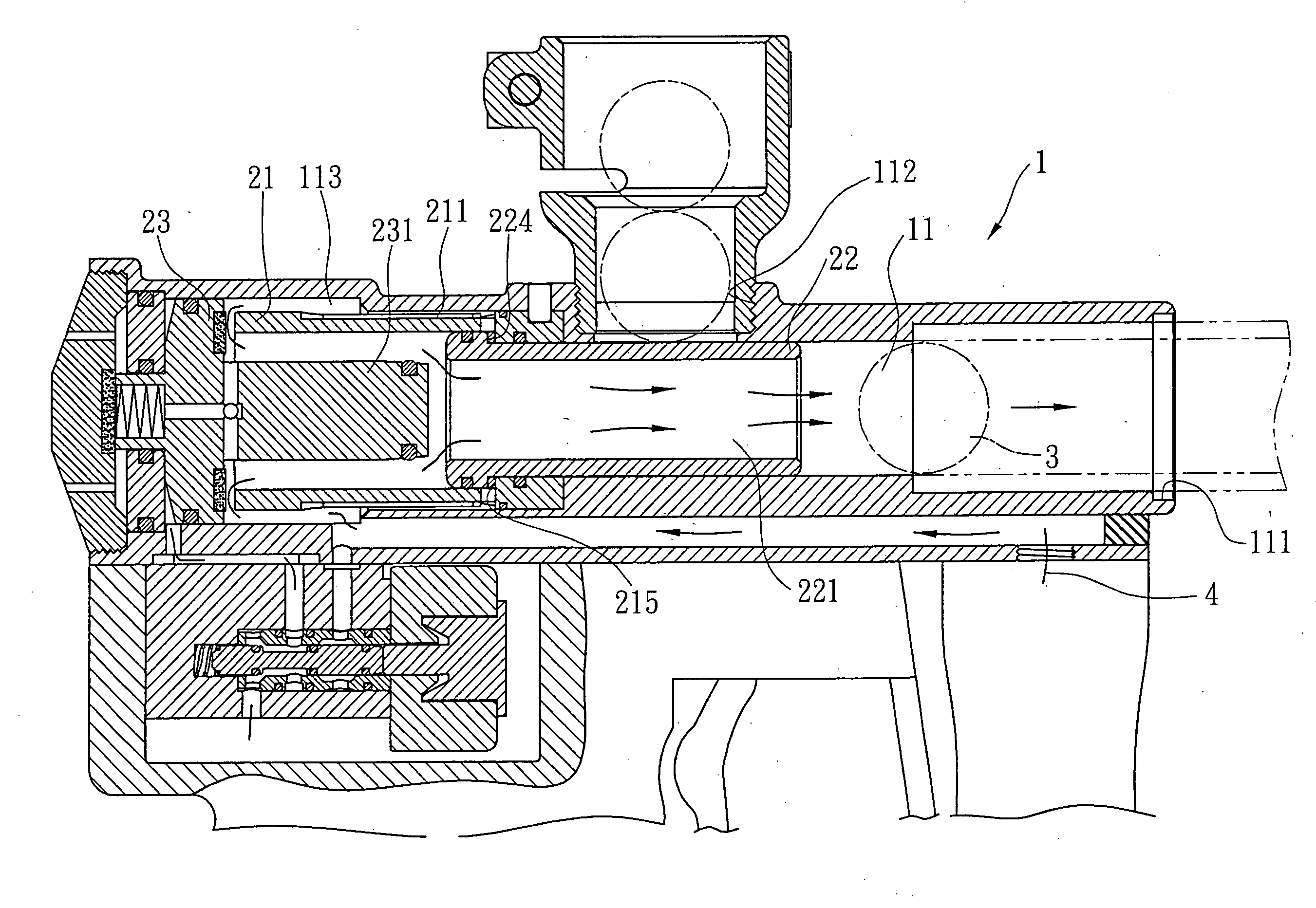
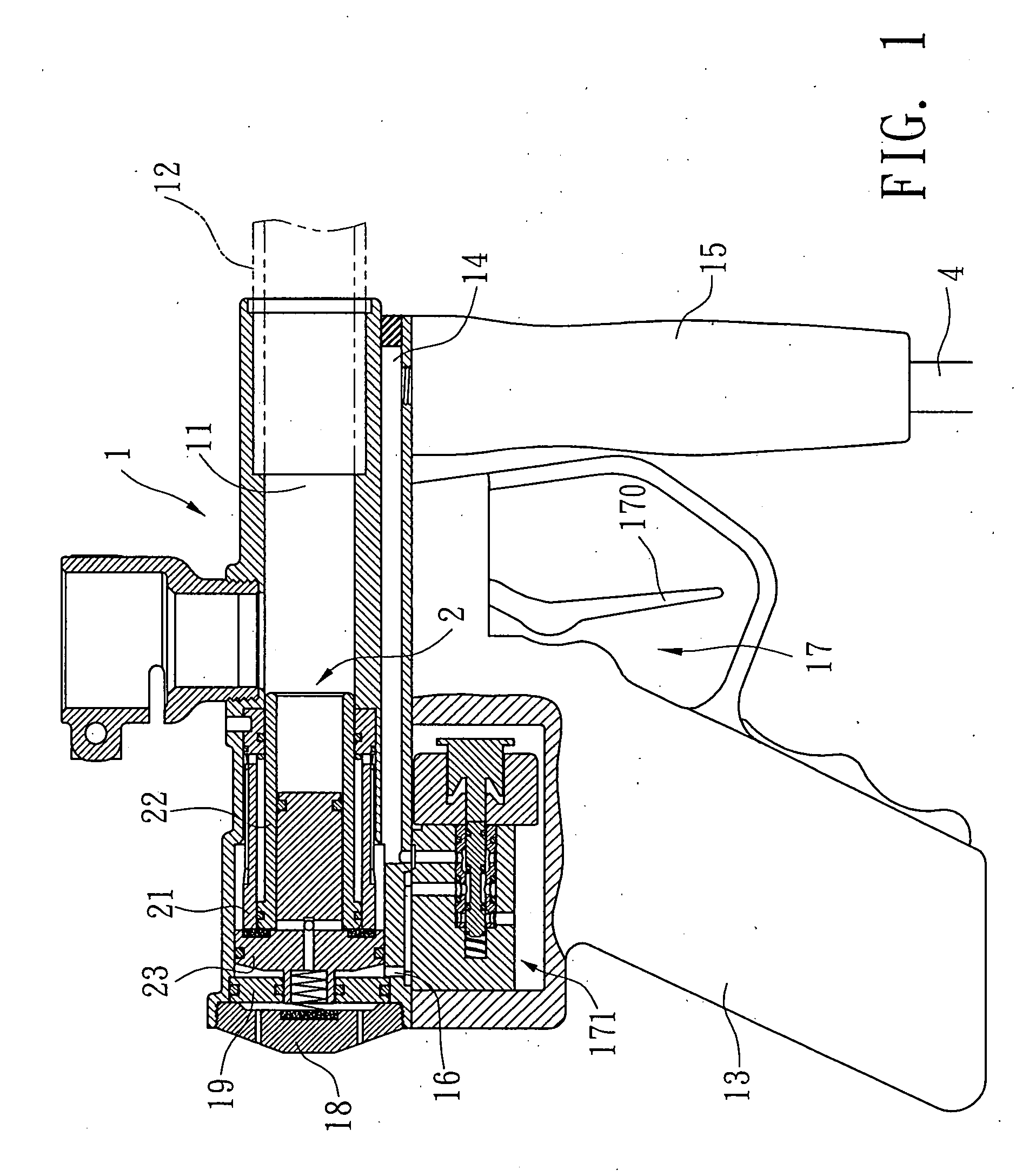
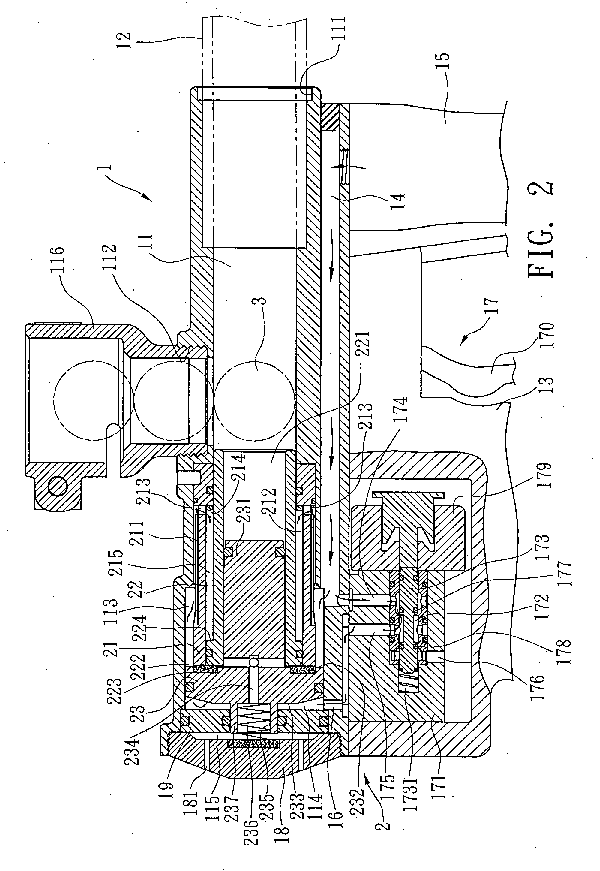
[0015]Please refer to FIGS. 1 and 2. The shooting structure of the paint bullet gun of the present invention is arranged in a gun body 1 of the paint bullet gun.

[0016]The gun body 1 is formed with an axial passage 11. A first end of the passage 11 is closed, while a second end of the passage 11 has an exit 111 for connecting with a barrel 12. In this embodiment, the first end of the passage 11 is sealed with a rear cap 18. The gun body 1 is formed with a bullet-dropping port 112 near the exit 111. The bullet-dropping port 112 communicates with the passage 11. A paint bullet 3 can be loaded into a magazine 116 and dropped through the bullet-dropping port 112 into the passage 11. The shooting structure 2 is arranged in the passage 11 on a first side of the bullet-dropping port 112 distal from the exit 111 for shooting the paint bullet 3 dropping into the passage 11. A handle 13 is arranged on one side of the gun body 1. A trigger unit 17 is disposed in the handle 13 for controlling th...


PUM


Abstract

A shooting structure of a paint bullet gun, which is arranged in a passage of a gun body of the paint bullet gun. The passage communicates with a bullet-dropping port. A handle is arranged on one side of the gun body. A trigger unit is disposed in the handle. The shooting structure includes a tubular member, a gunlock and a controlling member. The tubular member is disposed in the passage near the bullet-dropping port. In the passage, a gas reservoir is defined around the tubular member. The gas reservoir communicates with a gas supply via a pipeline. The gunlock is axially movably accommodated in the tubular member. The gunlock is formed with an axial exhaust duct. The gunlock is formed with a flange, whereby a space is defined between the gunlock and the tubular member. The gas reservoir communicates with the space. The controlling member has a guide stem extending toward the exhaust duct of the gunlock. The controlling member has a stopper face for shutting off the communication between the gas reservoir and the internal space of the tubular member. The controlling member further has a forced face partitioning the gas reservoir of the passage into an intake room.

Description

BACKGROUND OF THE INVENTION[0001]The present invention is related to a shooting structure of a paint bullet gun. In the paint bullet gun, one single gas supply is used to control movement of the gunlock as well as the shooting of the paint bullet.[0002]FIG. 6 shows a conventional shooting structures of a paint bullet gun. The barrel 6 of the paint bullet gun is formed with a passage 61 and a bullet-dropping port 63 communicating with the passage 61. One end of the passage 61 is a paint bullet exit 611. A gunlock 62 is disposed in the passage 61. The gunlock 62 respectively has a first cock 621a and a second cock 621b at a middle section and a rear section. The passage 61 has an isolating section 612 and a receiving section 613 respectively corresponding to the first and second cocks 621a, 621b. A first air chamber 614a and a second air chamber 614b are respectively formed on two sides of the isolating section 612. The barrel 6 is formed with a first intake section 64a and a second i...

Claims


Application Information

Patent Timeline
Patent Type & Authority Applications(United States)
IPC IPC(8): F41B11/00F41B11/62
CPCF41B11/721
Inventor LAI, BAO SHYAN
Owner LAI BAO SHYAN
Why Eureka
Try Eureka