Safety arrangement

a safety arrangement and vehicle technology, applied in the field of safety arrangements, can solve the problems of cabin occupant injuries, cabin deformation, and severe deceleration of vehicles, and achieve the effect of increasing the stiffness of the deformable elemen

Inactive Publication Date: 2008-01-17
AUTOLIV DEV AB
View PDF10 Cites 18 Cited by
  • Summary
  • Abstract
  • Description
  • Claims
  • Application Information

AI Technical Summary

Benefits of technology

[0014] Conveniently the deformable element has a predetermined range of deformation, (e.g. a deformation by 70% to 95% of its original length) and the sensor arrangement is connected to control the source of gas to supply to the or each chamber in response to a signal representative of an expected severity of crash that would lead to the deformable element being deformed by at least 50% of its predetermined range of deformation. Preferably the gas is only supplied if the expected severity of the crash is such that the deformable element is expected to be almost totally deformed, or deformed to such an extend that the stiffness of the deformable element will increase significantly.

Problems solved by technology

For a higher crash speed, the crumple zone will be totally compressed and other, stiffer parts of the vehicle will then absorb the remaining kinetic energy, but, with energy being absorbed by stiffer parts of the vehicle, the cabin of the vehicle may be subjected to very severe deceleration and may be deformed.
This is, of course, undesirable since severe deceleration imparted, by the cabin, to the occupant may cause injuries, and if the cabin deforms, again the consequence may be injuries for the cabin occupant.

Method used


Image

  • Safety arrangement
  • Safety arrangement
  • Safety arrangement

Examples


Embodiment Construction

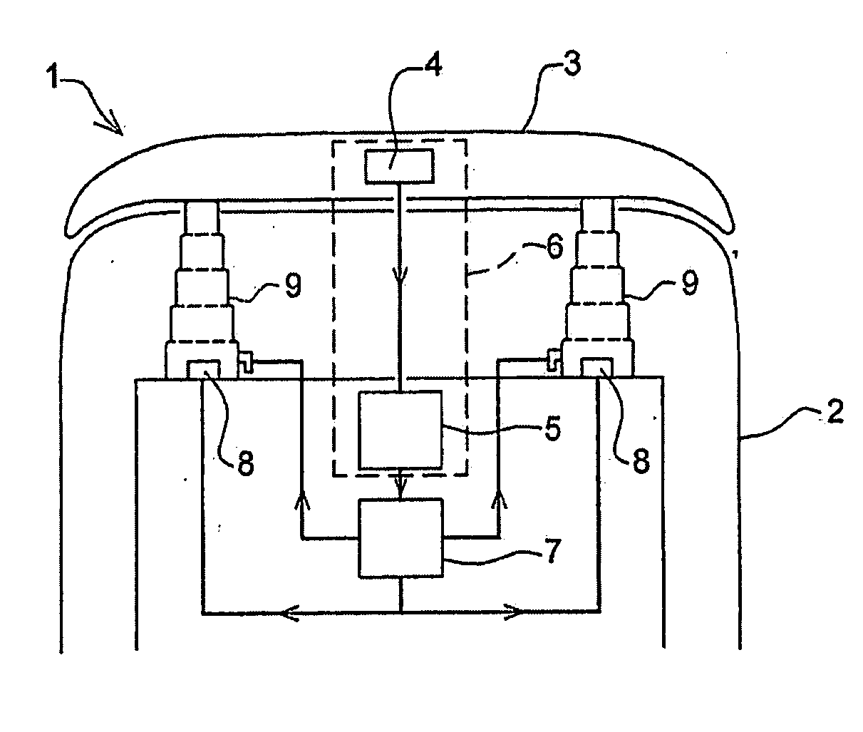
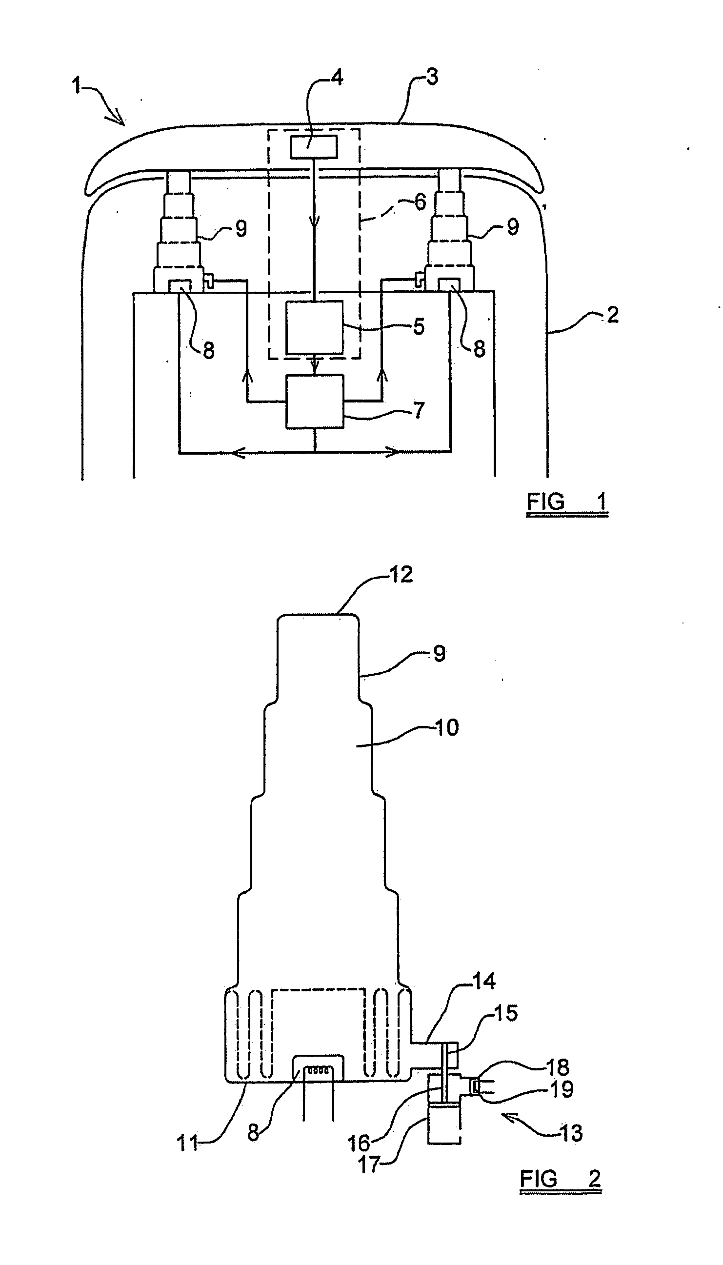
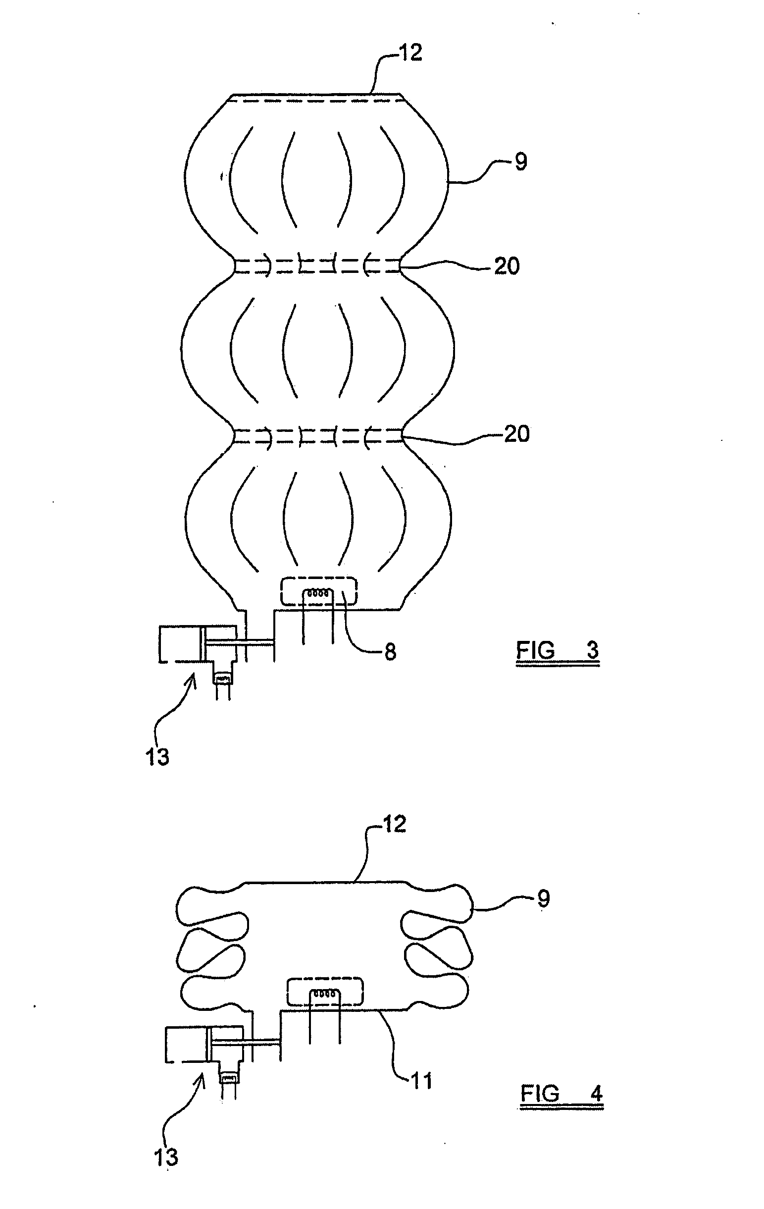
[0047] The preferred embodiments of the invention, which will be described below, provide a safety arrangement in which one or more energy-absorbing elements are provided which are intended to be compressed or crumpled in an accident situation to absorb energy. The energy-absorbing elements will be described as being associated with the front or rear bumpers of a vehicle but the energy-absorbing elements may be used at many different positions within a motor vehicle and may, effectively, be positioned between the seat of the vehicle and the vehicle itself, or may be located between the back-rest of the vehicle and the seat of the vehicle, or between the fixing points of the safety-belt and the vehicle. The energy-absorbing elements are designed to absorb all of the energy expected to be experienced in an accident within a range of severity. It is to be understood that in a very minor accident, the front or rear bumpers of the vehicle will absorb the impact, without the energy-absorb...


PUM


Abstract

A safety arrangement for use in a motor vehicle comprises at least one plastically-deformable element, defining an interior chamber, which will deform only when subjected to at least a first predetermined force. A source of gas is connected to inject gas into the chamber and a signal generator is provided to generate a signal representative of crash severity which is to be applied to the element during a crash situation or in an anticipated crash situation. The signal generator is connected to a control unit so as to provide the control unit with the signal. The control unit is connected to the source of gas in order to control the source of gas and to inject gas into the interior chamber of the deformable element so as to increase the gas pressure in the chamber when the crash severity signal is substantially in excess of a predetermined threshold. The arrangement provides a structure whose energy absorption characteristics can be varied according to the severity of a crash situation.

Description

CROSS REFERENCE TO RELATED APPLICATION [0001] This application claims priority to PCT / SE2006 / 000100, filed 25 Jan. 2006 and GB 0502074.8, filed 01 Feb. 2005. FIELD OF THE INVENTION [0002] The present invention relates to a safety arrangement for a motor vehicle, and more particularly relates to a safety arrangement to minimise the risk of injuries in a crash situation. [0003] In order to minimise the risk of injuries being sustained by a vehicle occupant in a crash situation, the occupant of the vehicle should be decelerated at as low peak and mean deceleration levels as possible, which means a mainly constant level during the whole crash event. Most modern motor vehicles include at least one restraint system to restrain an occupant within a seat in the cabin of the vehicle, and also most modern vehicles have arrangements which absorb kinetic energy at a substantially constant force level for the occupant during the accident situation. [0004] A typical vehicle may be provided with a...

Claims


Application Information

Patent Timeline
Patent Type & Authority Applications(United States)
IPC IPC(8): B60K28/10B60R21/16B60R19/20B60R19/36F16F7/12
CPCB60R19/205F16F7/125B60R19/36B60R19/20F16F7/1017
Inventor PIPKORN, BENGTHALAND, YNGVE
Owner AUTOLIV DEV AB
Why Eureka
Try Eureka