Eureka AIR delivers breakthrough ideas for toughest innovation challenges, trusted by R&D personnel around the world.

Motorized Trolley

a motorized trolley and trolley body technology, applied in the direction of lifting devices, load-engaging elements, hoisting equipment, etc., can solve the problems of complete standstill of the motorized trolley and consequently of the dragline device, prone to jamming or breaking, cumbersome gearboxes, etc., to reduce maintenance time and cost, compact height, and easy to design

Inactive Publication Date: 2008-01-17
IPALCO BV
View PDF3 Cites 0 Cited by
  • Summary
  • Abstract
  • Description
  • Claims
  • Application Information

AI Technical Summary

Benefits of technology

[0008] According to the invention, a motorized trolley for suspension from and travel on a rail comprises first and second supporting wheels for location on and engagement with opposite sides of the rail; the first supporting wheel comprising a first shaft for rotating the first wheel and the second supporting wheel comprising a second shaft for rotating the second wheel. According to an important aspect of the invention, a first driving motor is associated with the first shaft for rotating the first supporting wheel; and a second driving motor is associated with the second shaft for rotating the second supporting wheel. By providing an individual driving motor for each supporting wheel, the supporting wheels on each side of the rail can be individually driven. In case the rail comprises a corner, the supporting wheel on one side of the rail can be controlled to rotate slightly faster that the supporting wheel on the other side of the wheel as the motorized trolley goes through the corner region. Furthermore, one driving motor can compensate a failure of the other driving motor, so that the motorized trolley can still be moved. A failure of a driving motor does hence not automatically lead to a complete standstill of the motorized trolley and consequently of the dragline device. Maintenance and / or replacement of the faulty driving motor can be carried out at a convenient time, such as a scheduled stoppage of the dragline device. Using motorized trolleys according to the present invention can hence reduce maintenance time and costs.
[0018] The driving motors are preferably three-phase electric motors and the control unit preferably comprises a frequency changer for varying the speed of the driving motors by changing the control frequency. By controlling the frequency of the electric current fed to such driving motors, their speed, and consequently the speed of the motorized trolley, can easily be controlled.

Problems solved by technology

A failure of a driving motor does hence not automatically lead to a complete standstill of the motorized trolley and consequently of the dragline device.
Such gearboxes can be cumbersome and, due to their relatively high number of mechanical parts, prone to jamming or breaking.

Method used


Image

  • Motorized Trolley
  • Motorized Trolley

Examples


Embodiment Construction

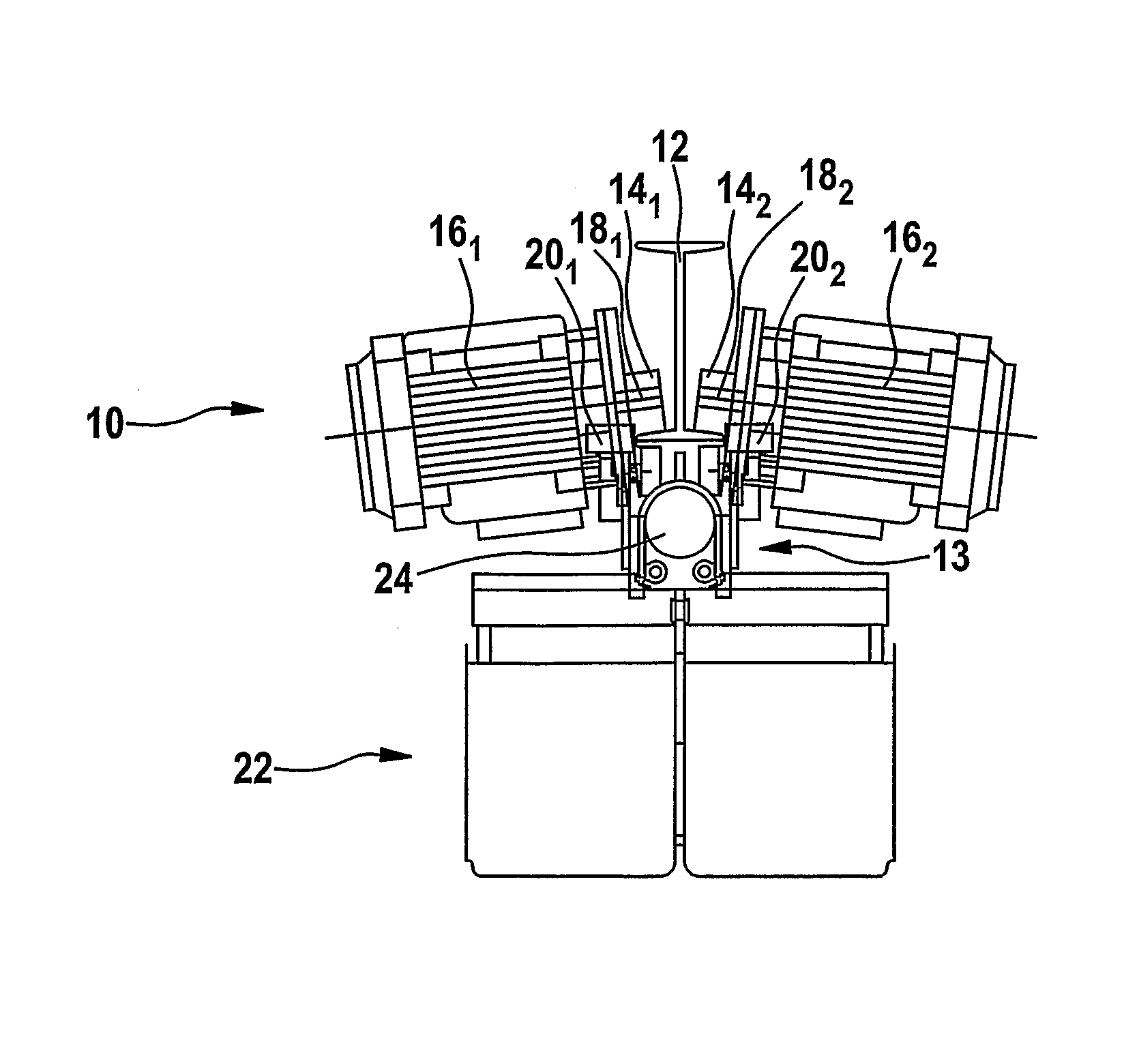
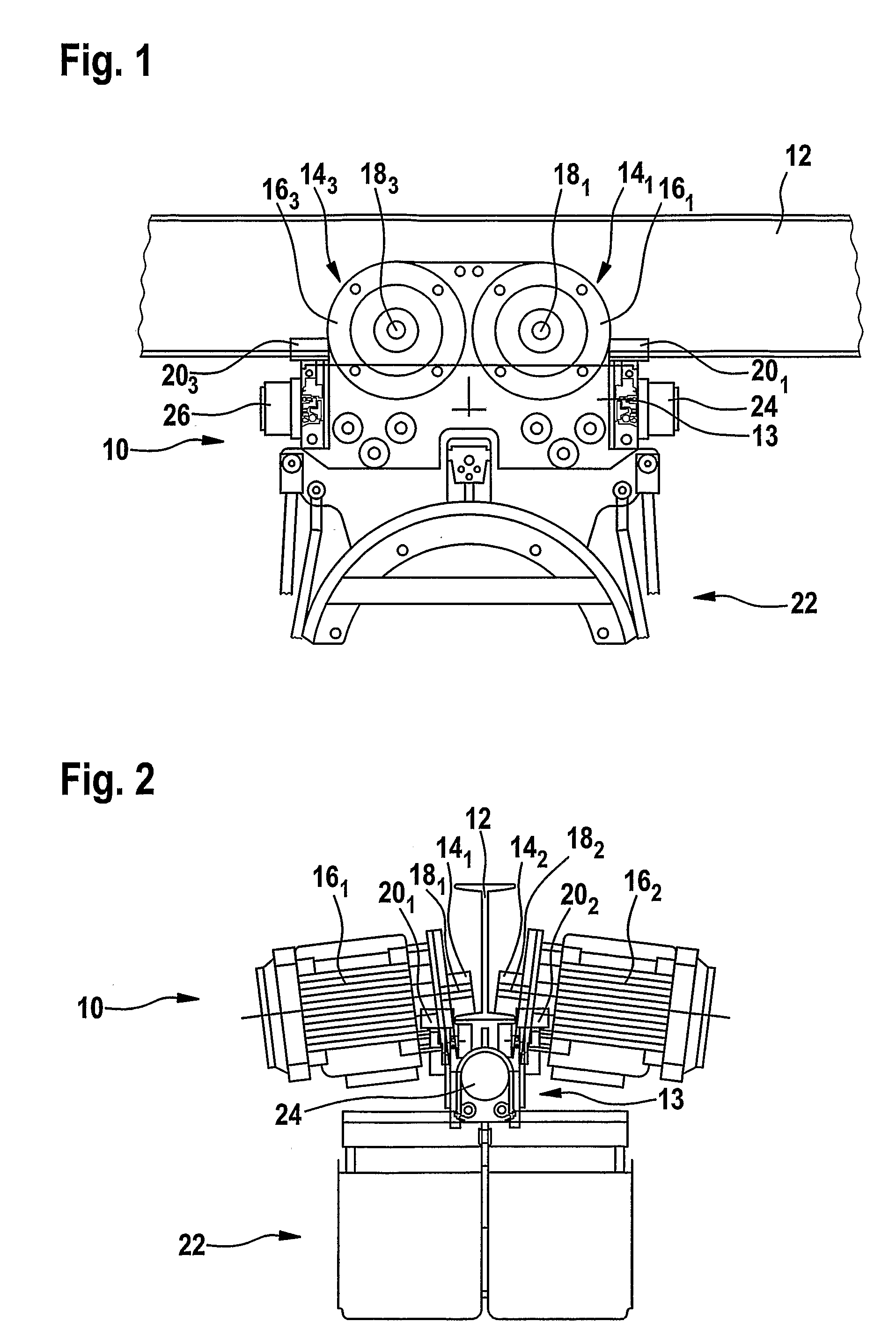
[0023]FIGS. 1 and 2 show a motorized trolley 10 for suspension from and travel on a rail 12 with a double-T cross-section, which is best shown in FIG. 2.

[0024] The motorized trolley 10 comprises a chassis 13 and is suspended by means of first, second, third and fourth supporting wheels 141, 142, 143, (the fourth supporting wheel cannot be seen in any of the Figures). The supporting wheels 141, 142, 143 run on the inner transverse surfaces of the lower (inverted) T. In each case, two supporting wheels, namely the first and third supporting wheels 141, 143 and the second and fourth supporting wheels 142 are arranged on opposite sides of the rail 12 respectively.

[0025] Each supporting wheel 141, 142, 143 has a driving motor 161, 162, 163 associated therewith. Each driving motor 161, 162, 163 comprises a driving shaft 181, 182, 183 which is connected to the associated supporting wheel 141, 142, 143, and which transmits rotational movement from the driving motor 161, 162, 163 to the su...


PUM


Abstract

A motorized trolley (10) for suspension from and travel on a rail (12) comprises first and second supporting wheels (14) for location on and engagement with opposite sides of the rail; the first supporting wheel comprising a first shaft (18-1) for rotating the first wheel (14-1) and the second supporting wheel (14-2) comprising a second shaft (18-2) for rotating the second wheel. Driving motors (16) are associated with the shafts for rotating the supporting wheels. Third and fourth supporting wheels may also be driven by motor. The motors are directly connected to the shafts of the supporting wheels.

Description

TECHNICAL FIELD [0001] The present invention generally relates to a motorized trolley for suspension from and travel on a rail, in particular motorized line trolley for use with a dragline device. BACKGROUND ART [0002] Line trolleys generally comprise a chassis having four supporting wheels and a line carrying device for carrying all sorts of cables or hoses connected between a stationary supply point and a moving piece of equipment. The support wheels are arranged so as to engage the rail from opposite sides and travel thereon. Passive line trolleys, i.e. line trolleys without their own drive have the disadvantage of rather abrupt acceleration of the individual trolleys by the previous one. This is damaging to the trolleys themselves and to the connection line therebetween. Furthermore, each time a further trolley is accelerated, the other trolleys are slowed down. [0003] In order to avoid this, motorized line trolleys have been proposed, wherein each line trolley is provided with ...

Claims


Application Information

Patent Timeline
Patent Type & Authority Applications(United States)
IPC IPC(8): B66F19/00
CPCB66C13/12
Inventor TOUKOLA, RISTO
Owner IPALCO BV
Why Eureka
Eureka Blog
Learn More