High Current Fast Rise And Fall Time LED Driver

a led driver and high current technology, applied in the direction of instruments, light sources, electroluminescent light sources, etc., can solve the problems of difficulty in switching current as quickly as needed, other limitations of the related art, and the current switching required is difficult with conventional means

Active Publication Date: 2008-01-17
MAXIM INTEGRATED PROD INC
View PDF100 Cites 54 Cited by
  • Summary
  • Abstract
  • Description
  • Claims
  • Application Information

AI Technical Summary

Benefits of technology

[0008] The present invention contemplates a variety of improved techniques for the fast switching of high amplitude current. A current shunting device can be utilized to divert a high amplitude current away from a load at high speed when activated, thus enab...

Problems solved by technology

The current switching required has been difficult with conventional means.
This suffers from many shortcomings, most importantly the difficulty in switching the current...

Method used


Image

  • High Current Fast Rise And Fall Time LED Driver
  • High Current Fast Rise And Fall Time LED Driver
  • High Current Fast Rise And Fall Time LED Driver

Examples


Embodiment Construction

[0017] In the following description, several specific details are presented to provide a thorough understanding of embodiments of the invention. One skilled in the relevant art will recognize, however, that the invention can be practiced without one or more of the specific details, or in combination with other components, etc. In other instances, well-known implementations or operations are not shown or described in detail to avoid obscuring aspects of various embodiments, of the invention.

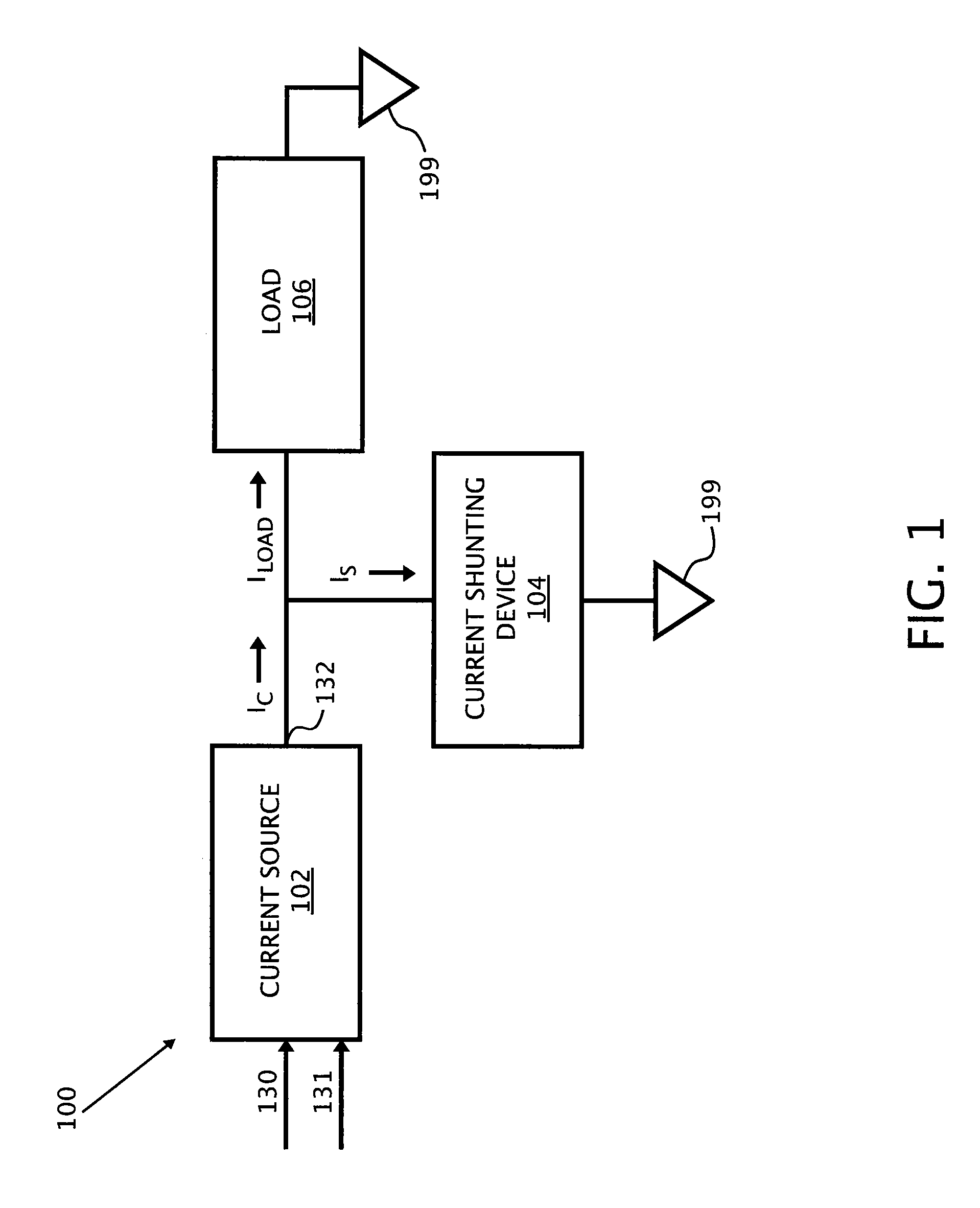
[0018]FIG. 1 is an exemplary block diagram of a high current fast rise and fall time load driver 100 according to one embodiment of the present invention. The load driver 100 includes current source 102, and one or more current shunting device 104 which is parallel coupled with a load 106 to a common ground 199. The current source 102 is a controlled current IC which may be in parallel with the current shunting device 104 and the load 106. An output 132 of the current source 102 is a controlled c...


PUM


Abstract

The present invention contemplates a variety of improved techniques for the fast switching of current through, among others, LED loads. A current shunting device is utilized to divert current away from a load at high speed when activated, thus enabling the control of the amount current that flows through the load.

Description

RELATED APPLICATIONS [0001] The present application claims priority to and is a utility patent application of Nalbant's U.S. Provisional Application No. 60 / 819,049, filed Jul. 7, 2006, entitled HIGH CURRENT FAST RISE AND FALL TIME LED DRIVERS, which is hereby incorporated by reference.BACKGROUND [0002] 1. Field of Invention [0003] This invention relates to the field of high current LED driver. [0004] 2. Background of the Invention [0005] High brightness and high current light emitting diodes (LED) are increasingly being used as high intensity light sources. High intensity LEDs provide many benefits over other high intensity light sources, such as longer life, wider color range, less hazardous operating voltages, and higher efficiency. In some rear projection TVs and front projection systems the light from an LED is required to be switched very rapidly as required by the Digital Micromirror Device (DMD). [0006] The digital micromirror device (DMD) imager is a digital light valve that...

Claims


Application Information

Patent Timeline
IPC IPC(8): H05B37/02
CPCH05B33/0818H05B45/3725H05B45/375
Inventor NALBANT, MEHMET
Owner MAXIM INTEGRATED PROD INC
Why Eureka
Try Eureka