Imaging apparatus

a technology of imaging apparatus and rotary dial, which is applied in the field of imaging apparatus, can solve the problems of low operability, improper operation, and the rotary dial may not exist at an easily visible position in the shooting through the finder, so as to improve operability, easy to grasp, and easy to see

Inactive Publication Date: 2008-01-17
SONY CORP
View PDF8 Cites 10 Cited by
  • Summary
  • Abstract
  • Description
  • Claims
  • Application Information

AI Technical Summary

Benefits of technology

[0009]However, since an imaging apparatus in the past includes the rotary dial in an end part of the body of the apparatus on the user side, the rotary dial may not exist at an easily visible position in shooting through a finder. For this reason, the rotary dial may be operated gropingly, which lowers the operability.
[0010]Furthermore, since the rotary dial is provided in an end part of the body of the apparatus on the user side, the rotary dial may rotate as a result of the unintentional contact with a user in shooting, which may cause an improper operation. In order to prevent this problem, some imaging apparatus has a reclosable cover for the rotary dial. However, providing the cover increases the number of parts, and, in addition, the cover may be necessary to open every time the rotary dial is to be used and to close every time the rotary dial is not used.
[0011]Accordingly, it is desirable to propose an imaging apparatus for overcoming those problems and improving the ease of use.

Problems solved by technology

However, since an imaging apparatus in the past includes the rotary dial in an end part of the body of the apparatus on the user side, the rotary dial may not exist at an easily visible position in shooting through a finder.
For this reason, the rotary dial may be operated gropingly, which lowers the operability.
Furthermore, since the rotary dial is provided in an end part of the body of the apparatus on the user side, the rotary dial may rotate as a result of the unintentional contact with a user in shooting, which may cause an improper operation.
However, providing the cover increases the number of parts, and, in addition, the cover may be necessary to open every time the rotary dial is to be used and to close every time the rotary dial is not used.

Method used


Image

  • Imaging apparatus
  • Imaging apparatus
  • Imaging apparatus

Examples


Embodiment Construction

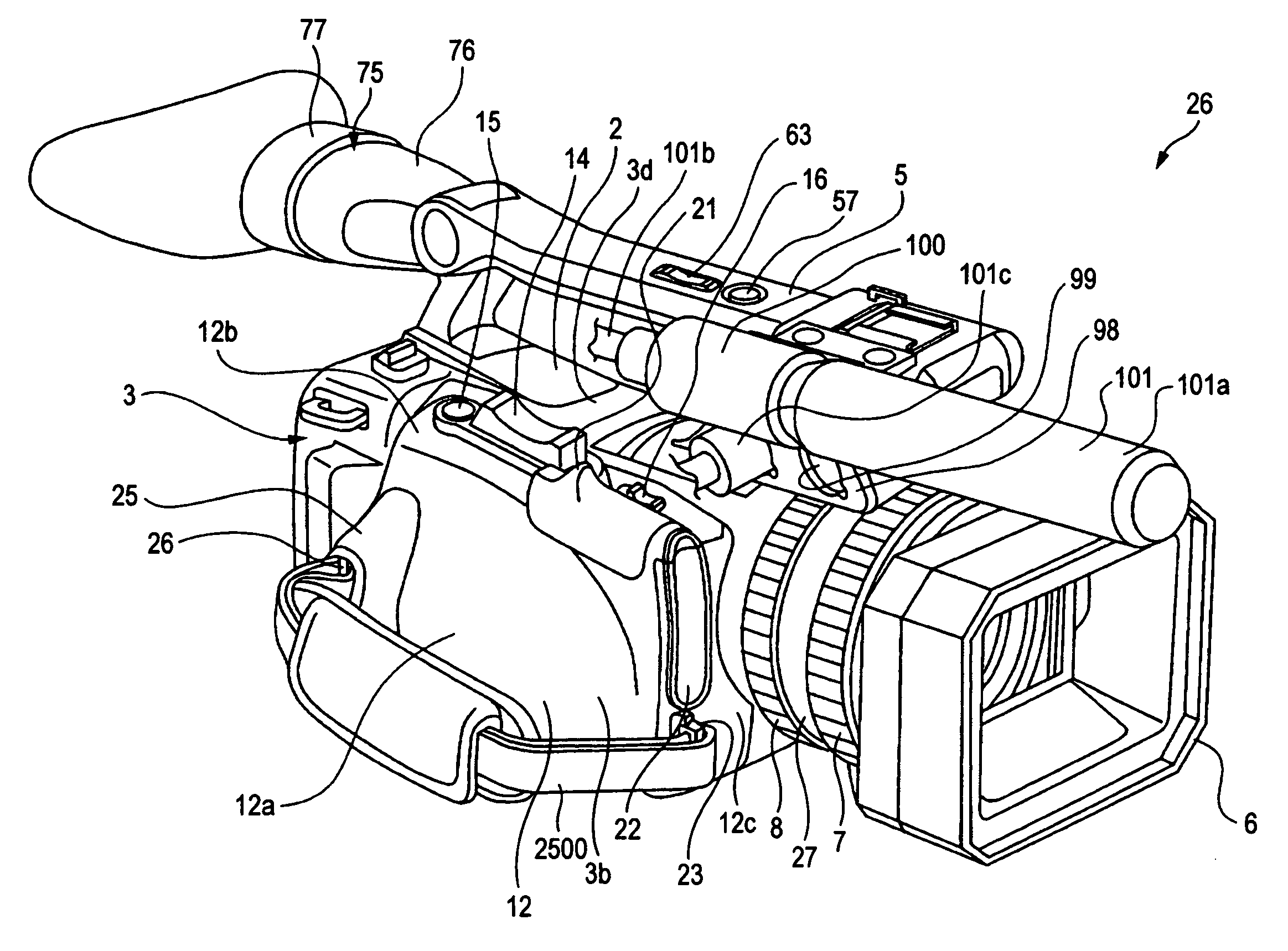
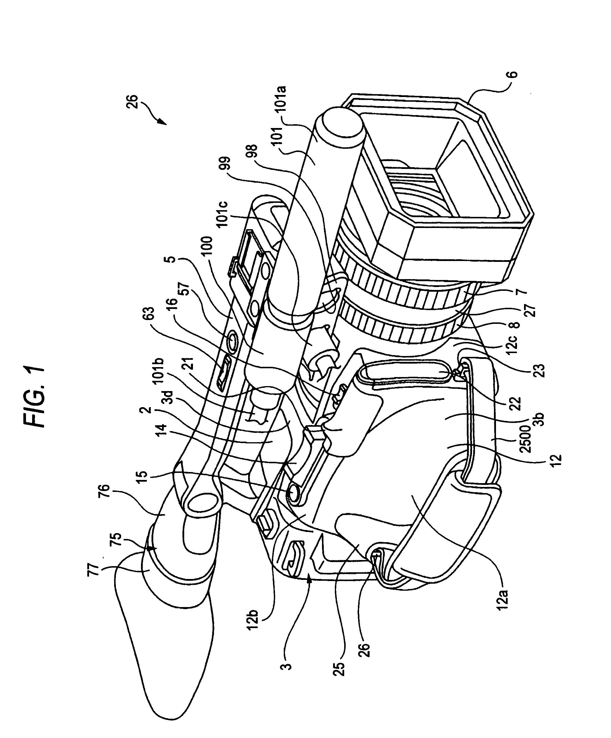
[0071]With reference to attached drawings, an embodiment of the invention will be described in detail below.

[0072]The invention is applied to a video camera in an embodiment below. The scope of the application of the invention is not limited to a video camera but is widely applicable to a video camera and other imaging apparatus that shoots images.

[0073]The front and back, top and bottom and left and right directions are about a photographer (user) in shooting with a video camera in the description below. Therefore, the subject side is front while the photographer side is back. The front and back, top and bottom and left and right directions are only for the convenience of the description, and embodiments of the invention are not limited to the directions.

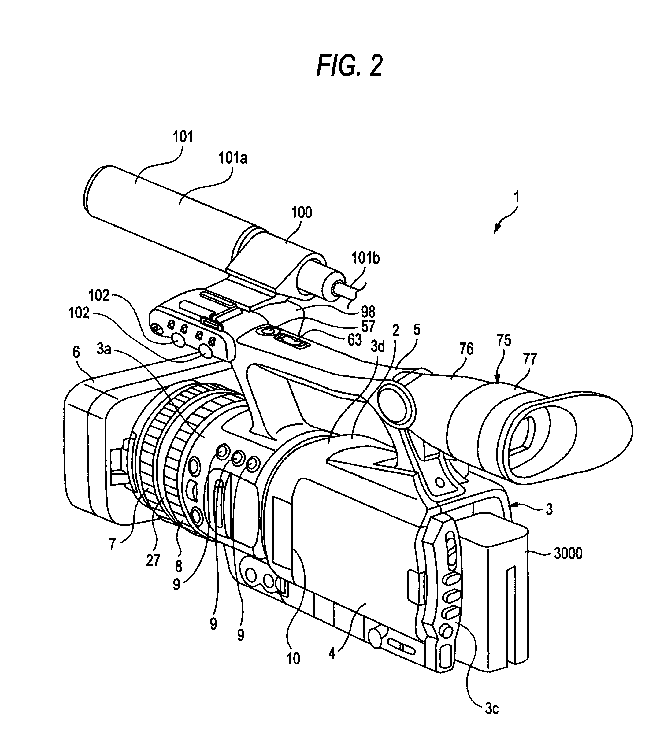
[0074]An imaging apparatus (that is, a video camera, which is an electronic appliance) 1 includes necessary components inside and outside of a cabinet 2 (refer to FIGS. 1 to 4).

[0075]The imaging apparatus 1 includes, as shown in FI...


PUM


Abstract

An imaging apparatus includes a handle provided above the body of the imaging apparatus and extending in the direction connecting a subject and a user, a voice input terminal on one side surface at the end of the handle on the subject side, to which a connector connecting to a microphone is to be connected, and a rotary dial on the opposite side surface of the one side surface at the end of the handle on the subject side, the rotary dial adjusting voice signals input through the voice input terminal.

Description

CROSS REFERENCES TO RELATED APPLICATIONS[0001]The present invention contains subject matter related to Japanese Patent Application JP 2006-192083 filed in the Japanese Patent Office on Jul.12, 2006, the entire contents of which being incorporated herein by reference.BACKGROUND OF THE INVENTION[0002]1. Field of the Invention[0003]The present invention relates to a technical field relating to an imaging apparatus. In particular, the invention relates to a technical field for improving the ease of use by providing a voice input terminal and a rotary dial for adjusting voice signals on opposite sides against each other about a handle.[0004]2. Description of the Related Art[0005]An imaging apparatus such as a video camera has a handle to be grasped by a photographer (user) for shooting, for example, above the body of the apparatus (refer to JP-A-2006-74695 (Patent Document 1), for example).[0006]Some imaging apparatus, such as a video camera, having the handle may have a voice input term...

Claims


Application Information

Patent Timeline
Patent Type & Authority Applications(United States)
IPC IPC(8): H04N5/225
CPCH04N5/2251H04N23/531
Inventor OSHIMA, MASAAKI
Owner SONY CORP
Why Eureka
Try Eureka