Transflective liquid crystal display device

a liquid crystal display and liquid crystal display technology, applied in non-linear optics, instruments, optics, etc., can solve problems such as display quality degradation, and achieve the effect of improving the display quality of the transflective liquid crystal display devi

Inactive Publication Date: 2008-01-17
PANASONIC LIQUID CRYSTAL DISPLAY CO LTD +1
View PDF10 Cites 21 Cited by
  • Summary
  • Abstract
  • Description
  • Claims
  • Application Information

AI Technical Summary

Benefits of technology

[0051]According to the invention, it is possible to improve the display quality in the transflective liquid crystal display device.

Problems solved by technology

Upon black display in the transmission portion, an electric field is not generated between the pixel electrode and the counter electrode of the transmission portion and it is supposed that when the electric field between the counter electrode of the transmission portion and the counter electrode of the reflection portion should leak to the transmission portion, liquid crystals are rotated to form a light leakage portion to result in the degradation of display quality.

Method used


Image

  • Transflective liquid crystal display device
  • Transflective liquid crystal display device
  • Transflective liquid crystal display device

Examples


first embodiment

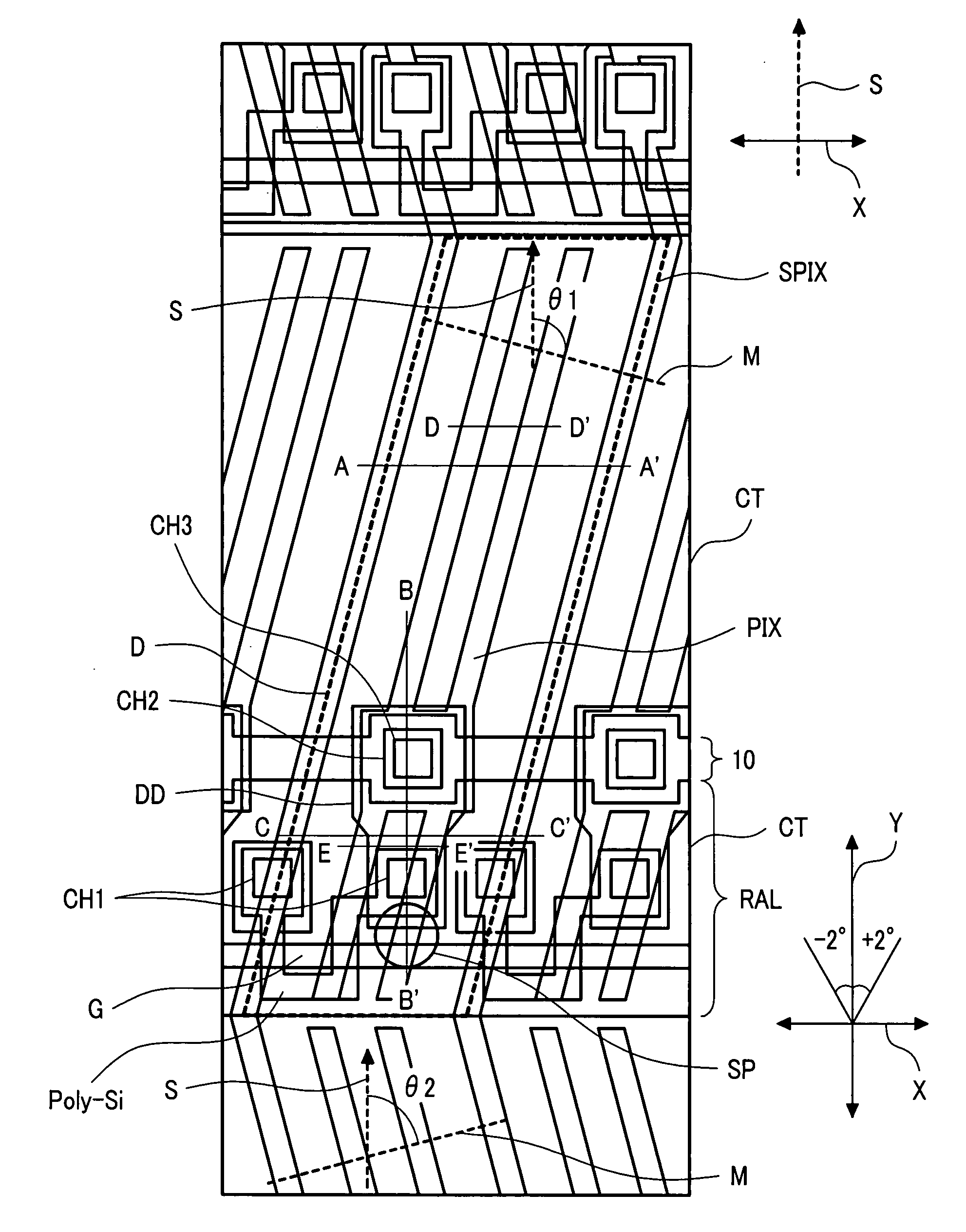
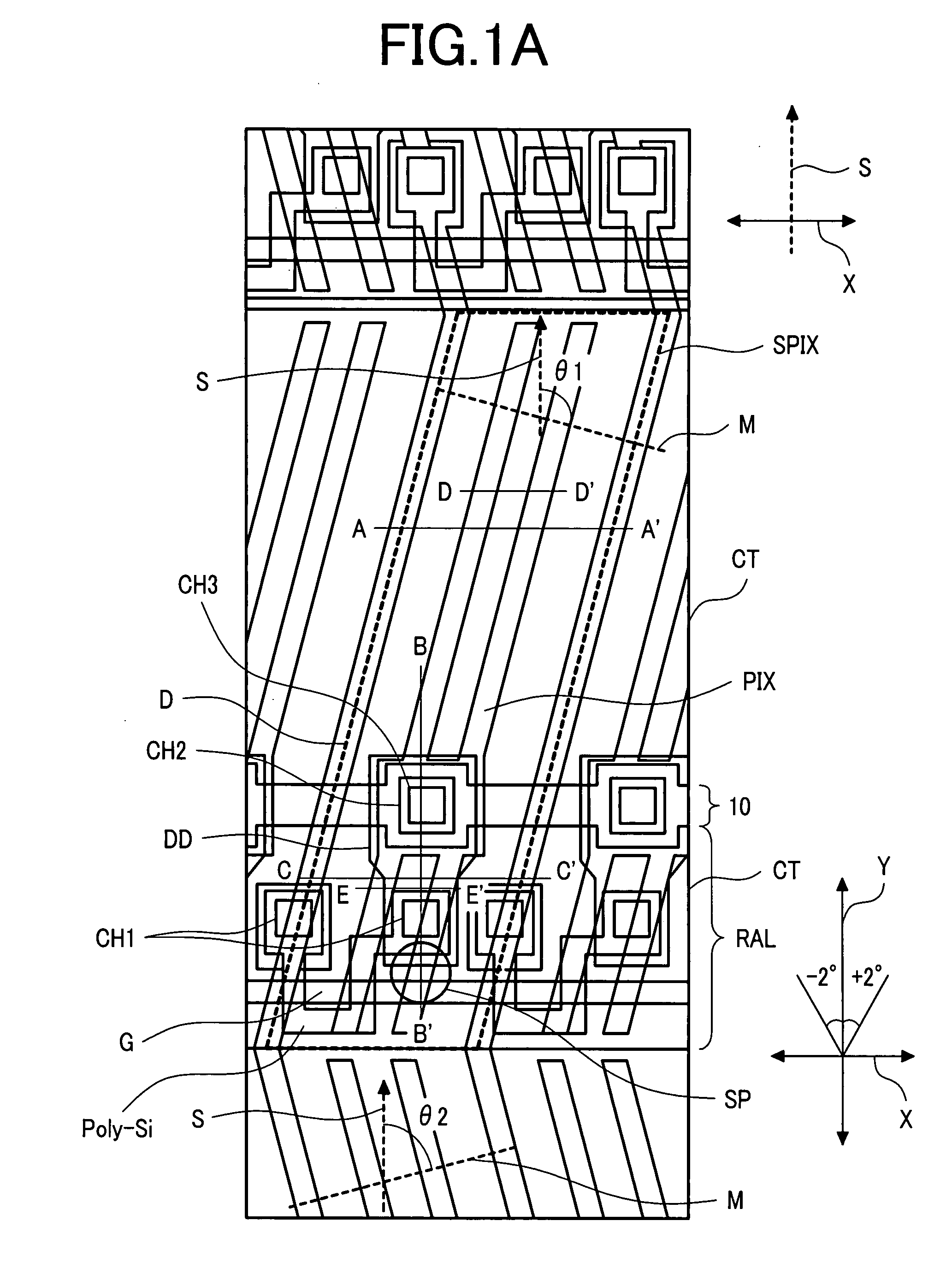
[0099]FIG. 1A is a plan view showing an electrode structure of a sub-pixel in a transflective liquid crystal display device of a first embodiment according to the invention.

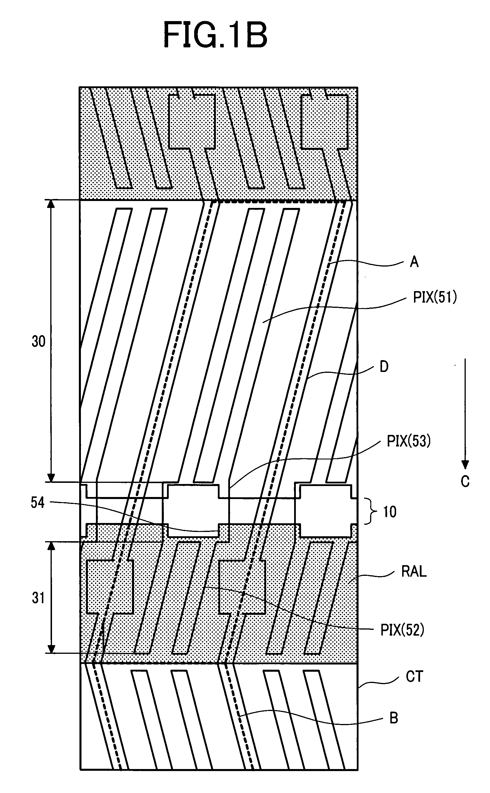
[0100]FIG. 1B is a view showing only the pixel electrode, counter electrode, reflection electrode, and video line among those shown in FIG. 1A. In FIG. 1B, portions shown by dotted line frames A, B show 1 sub-pixel respectively.

[0101]As shown in FIG. 1B, also in the first embodiment, the pixel electrode (PIX) is common in the 1 sub-pixel, the counter electrodes (CT) are independent between the transmission portion 30 and the reflection portion 31. That is, the counter electrode (CT) is bisected to the transmission portion and the reflection portion. Then, a reflection electrode (RAL) is formed above the counter electrode (CT) of the reflection portion 31.

[0102]FIG. 1B illustrates a case of constituting a counter electrode (CT) of the reflection portion 31 in one display line (display line having sub-pixel shown b...

second embodiment

[0165]FIG. 10 is a plan view showing the electrode structure of a sub-pixel of a transflective liquid crystal display device as a second embodiment of the invention.

[0166]The transflective liquid crystal display device of the second embodiment basically has the same constitution as that in the first embodiment described previously and is different for the following constitutions.

[0167]That is, in the first embodiment described above, as shown in FIG. 1A and FIG. 1B, θ is made identical for the transmission portion 30 and the reflection portion 31 in the 1-sub-pixel. However, in the second embodiment as shown in FIG. 10, θ is made different between the transmission portion 30 (θ3) and the reflection portion 31 (θ4) in the 1-sub-pixel. The bending angle of the comb-shaped electrode 51 for the transmission portion and the comb-shaped electrode 52 for the reflection portion of the pixel electrode (PIX) is changed. Since θ3 and θ4 can be set optionally, the degree of freedom of design fo...

third embodiment

[0176]FIG. 12 to FIG. 17 are views for a transflective liquid crystal display device as a third embodiment of the invention in which:

[0177]FIG. 12 is a plan view showing an electrode structure of a sub-pixel;

[0178]FIG. 13 is a cross sectional view for a main portion showing a cross sectional structure along line F-F′ in FIG. 12;

[0179]FIG. 14 is a cross sectional view for a main portion showing a cross sectional structure along line G-G′ in FIG. 12;

[0180]FIG. 15 is a cross sectional view for a main portion showing a cross sectional structure along line H-H′ in FIG. 12;

[0181]FIG. 16 is a cross sectional view for a main portion showing a cross sectional structure on the side of a substrate provided with a support spacer shown in FIG. 12; and

[0182]FIG. 17 is a cross sectional view for a main portion showing a cross sectional structure along line I-I′ and line J-J′ in FIG. 12.

[0183]The transflective liquid crystal display device of the third embodiment basically has the same constitution...


PUM

PropertyMeasurementUnit
thicknessaaaaaaaaaa
thicknessaaaaaaaaaa
thicknessaaaaaaaaaa

Abstract

A transflective liquid crystal display device with improved display quality in which the liquid initial alignment direction of the liquid crystal layer is in a direction perpendicular to the extending direction of a clearance between the counter electrode of a transmission portion and a counter electrode of a reflection portion or in a direction within a range of ±2° in the clockwise direction perpendicular to the extending direction of the clearance in a case where the liquid crystal layer comprises positive type liquid crystals, or the liquid crystal initial alignment direction of the liquid crystal layer is in a direction parallel with the extending direction of a clearance, or a direction within a range of ±2° in the clockwise direction relative to the extending direction of the clearance in a case where the liquid crystal layer comprises negative type liquid crystals.

Description

CLAIM OF PRIORITY[0001]The present application claims priority from Japanese Application JP 2006-193485 filed on Jul. 14, 2006, the content of which is hereby incorporated by reference into this application.BACKGROUND OF THE INVENTION[0002](1) Field of the Invention[0003]The present invention concerns a transflective liquid crystal display device and, more specifically, it relates to a technique which is effective to the application for IPS system transflective liquid crystal display devices.[0004](2) Description for the Related Art[0005]A transflective liquid crystal display device having a transmission portion and a reflection portion in a 1 sub-pixel has been used as a display for use in portable equipments.[0006]For the transflective liquid crystal display device, a vertical electric field system for driving liquid crystals by applying an electric field to liquid crystals put between a pair of substrates in a direction vertical to the substrate plane of the pair of substrates ha...

Claims


Application Information

Patent Timeline
Patent Type & Authority Applications(United States)
IPC IPC(8): G02F1/1335
CPCG02F1/133555G02F2001/134345G02F1/134363G02F1/1337G02F1/134345
Inventor OCHIAI, TAKAHIROMIYAZAWA, TOSHIOMAKI, MASAHIROSASAKI, TOHRUMORIMOTO, MASATERU
Owner PANASONIC LIQUID CRYSTAL DISPLAY CO LTD
Why Eureka
Try Eureka