Contact lens

a contact lens and lens technology, applied in the field of contact lenses, can solve the problems of blurred vision and contrast loss, poor positioning of specific wave patterns and their locations, and poor positioning of other types of contact lenses, and achieve the effect of improving the positioning of contact lenses on the ey

Inactive Publication Date: 2008-01-17
PROCORNEA NEDERLAND
View PDF11 Cites 23 Cited by
  • Summary
  • Abstract
  • Description
  • Claims
  • Application Information

AI Technical Summary

Benefits of technology

[0009]The invention aims to improve positioning of a conta...

Problems solved by technology

Bifocal and multi focal soft lenses are mostly used by people reaching the 40+ age and have a need for a reading addition into their contact lenses, so called presbyopic patients Many multi focal lens designs are on the market nowadays but so far with very limited success, due to the fact that a soft lens is not moving on the eye like a RGP lens and theref...

Method used


Image

  • Contact lens
  • Contact lens
  • Contact lens

Examples


Embodiment Construction

[0044]In this description of embodiments, similar reference numbers are used to indicate similar features throughout the embodiments.

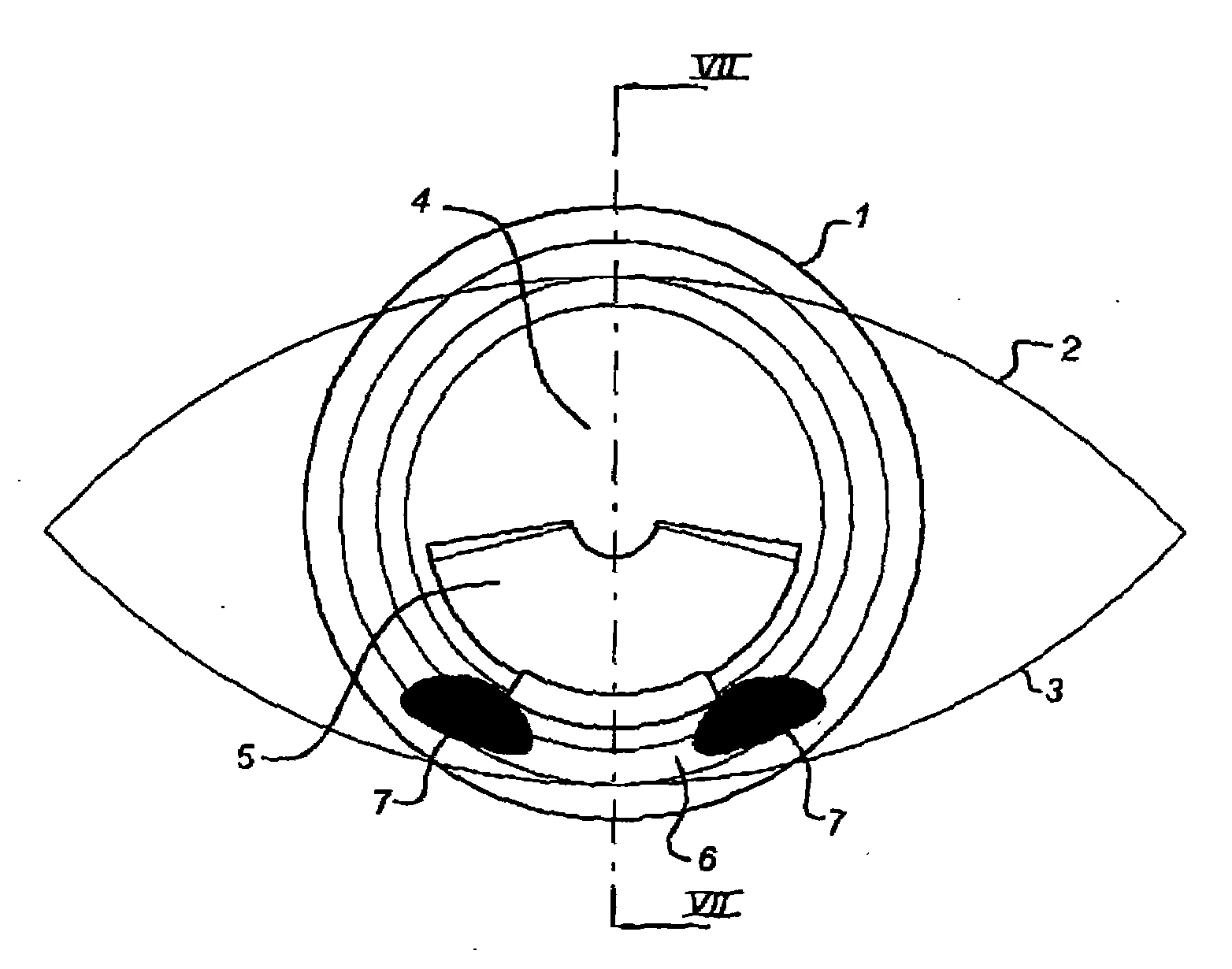
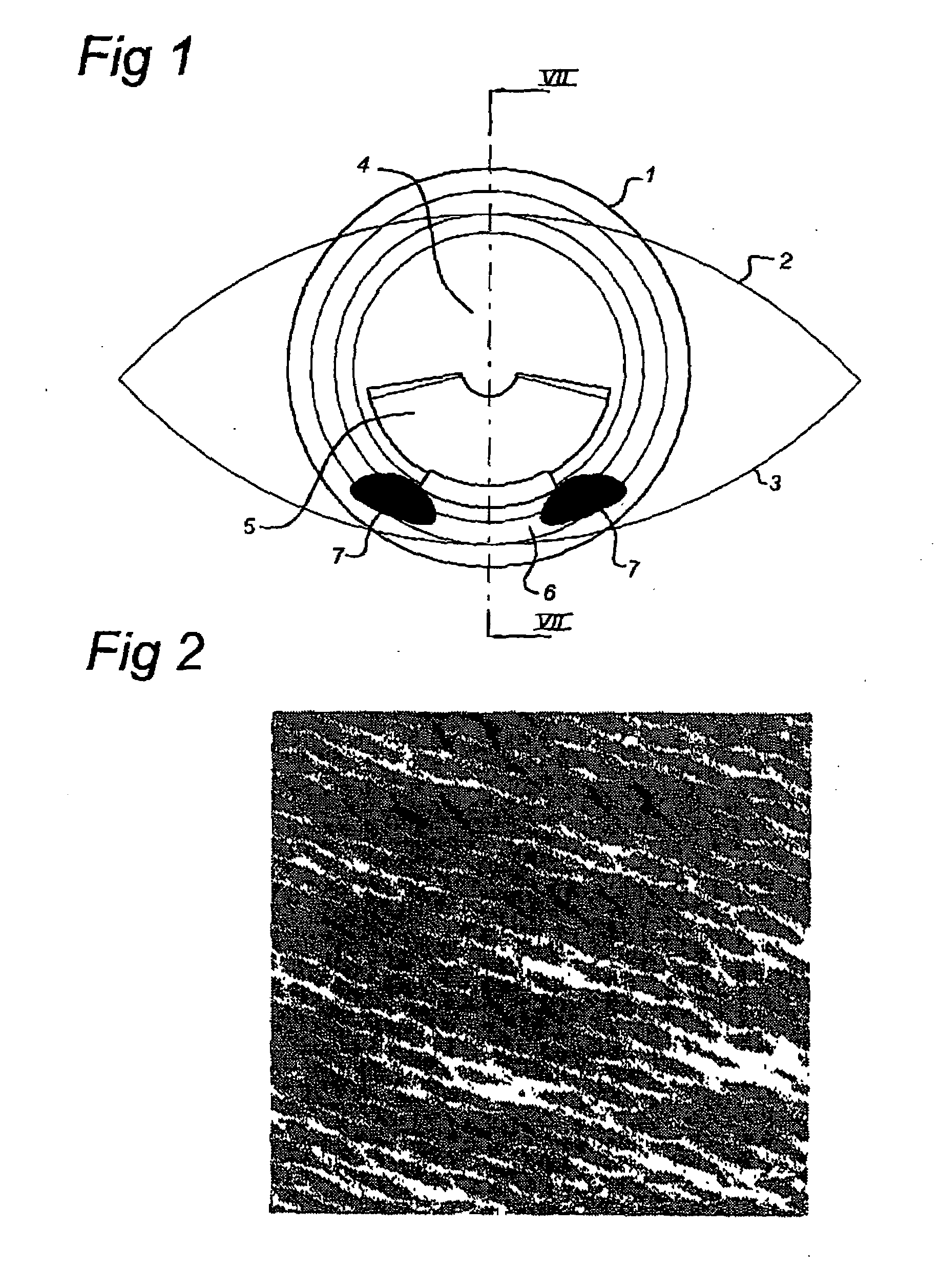
[0045]FIG. 1 shows a first embodiment of a contact lens 1 on an eye with upper eyelid 2 and lower eyelid 3. Contact lens 1 has an optical zone with a central optical zone 4 and a presbyopia correcting further optical zone 5 radially outside the central optical zone.

[0046]Around the further optical zone 5, contact lens 1 has a ramped ridge 6 which has several friction areas 7 on the ridge below the further optical zone 5.

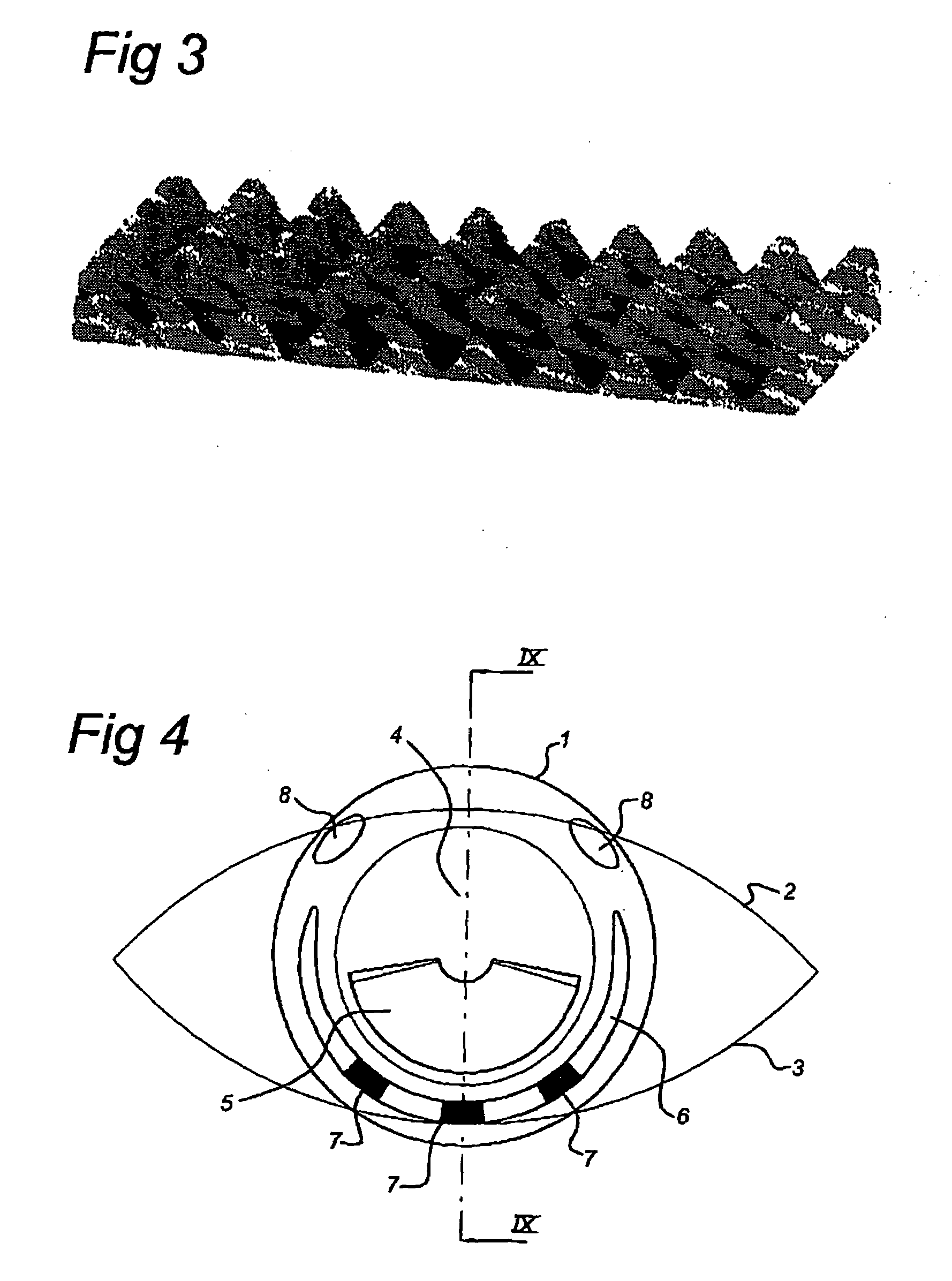
[0047]FIG. 2 shows an example of a friction area according to the invention, in which a SEM picture is shown of a friction area which has a sinusoid surface with an amplitude of at least 2.5 μm and a wavelength of about 70 μm in both the x- and y-directions. The sinusoids in this embodiment have sub-μm form accuracy with a surface finish on the order of 100 nm. These types of sinusoidal surfaces can be machined using a single point diam...


PUM


Abstract

The invention relates to a contact lens comprising at least one area with an increased friction for an eyelid for providing grip to the eyelid for positioning the contact lens on an eye in use, wherein said friction area comprises micro scale undulations for providing friction between an eyelid and the contact lens.

Description

BACKGROUND[0001]The present invention relates to a contact lens, in particular a contact lens for which the position or the orientation on the eye is of importance.[0002]In particular soft contact lenses have solved some of the problems that patients have experienced in not being able to wear rigid gas permeable (RGP) contact lenses, or in not being able to wear them for a longer period of time, because of initial discomfort.[0003]Bifocal and multi focal soft lenses are mostly used by people reaching the 40+ age and have a need for a reading addition into their contact lenses, so called presbyopic patients Many multi focal lens designs are on the market nowadays but so far with very limited success, due to the fact that a soft lens is not moving on the eye like a RGP lens and therefore the small optic central part of the lens has to be a optical everything in one design, causing blurred vision and lost of contrast.[0004]The most successful design for presbyopic patient is a translat...

Claims


Application Information

Patent Timeline
IPC IPC(8): G02C7/04
CPCG02C7/048G02C7/041
Inventor WANDERS, BERNARDUS FRANCISCUS MARIA
Owner PROCORNEA NEDERLAND
Why Eureka
Try Eureka