Lamp for vehicle

a technology for vehicles and lamps, applied in vehicle headlamps, gas-filled discharge tubes, lighting support devices, etc., can solve the problems of increasing the number of man-hours necessary to mount difficult to mount adjacent semiconductor light emitting chips, and difficulty in reducing pitch dimensions, etc., to achieve the effect of easy obtaining desired light distribution characteristics

Inactive Publication Date: 2008-01-17
KOITO MFG CO LTD
View PDF4 Cites 70 Cited by
  • Summary
  • Abstract
  • Description
  • Claims
  • Application Information

AI Technical Summary

Benefits of technology

[0007]Exemplary embodiments of the present invention provide a lamp for a vehicle capable of

Problems solved by technology

In the light source of 2004-362840, plural semiconductor light emitting chips are mounted on the front surface of the substrate in the matrix state, so that when the number of semiconductor light emitting chips is increased in order to improve luminous intensity of the light source, the number of man-hours necessary to mount the semiconductor light emitting chips increases and also it is difficult to mount the adjacent semiconductor light emitting chips in a predetermined position of the substrate and in a predetermined optical axis direction.
Particularly, a required spacing (pitch) between the adjacent semiconductor light emitting chips must be ensured in order to mount the semiconductor light emitting chips, and as a re

Method used


Image

  • Lamp for vehicle
  • Lamp for vehicle
  • Lamp for vehicle

Examples


first exemplary embodiment

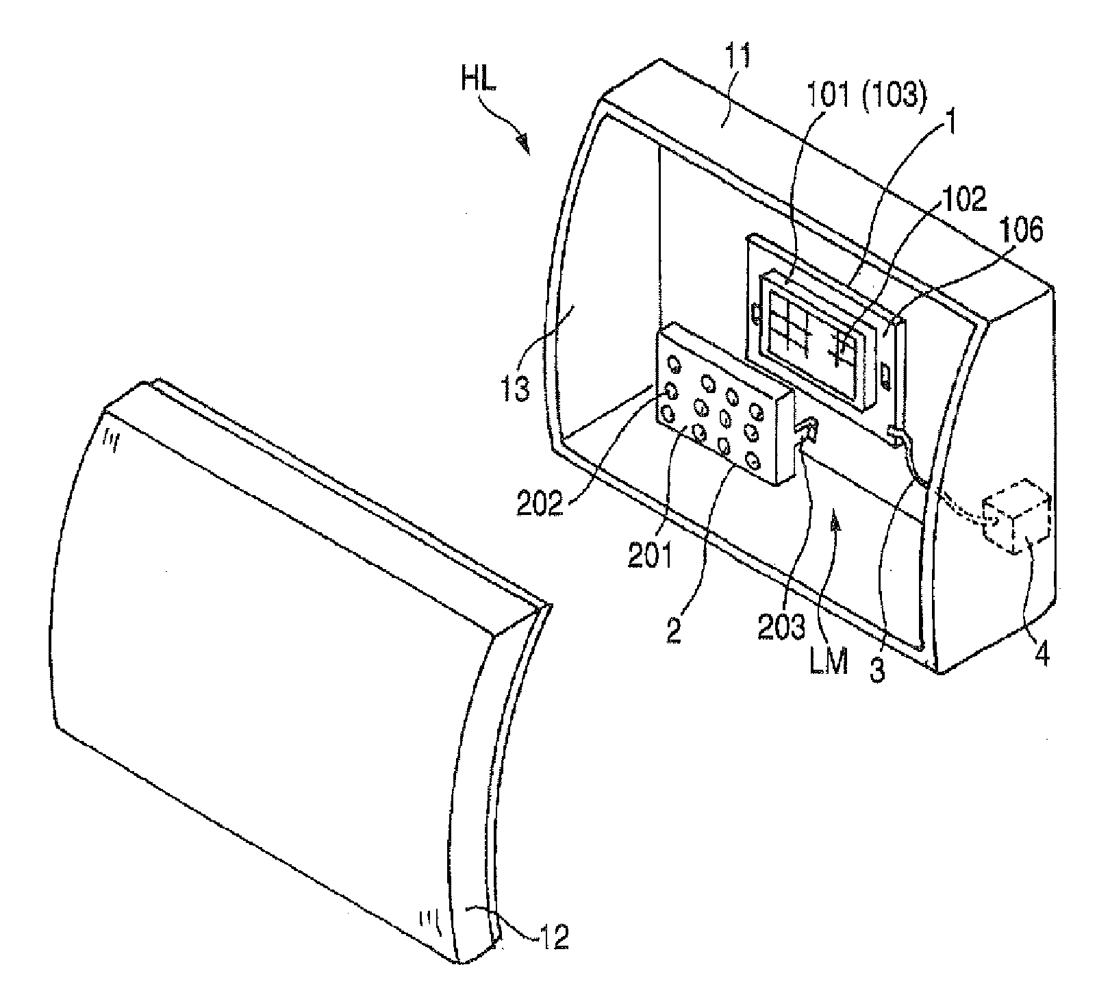
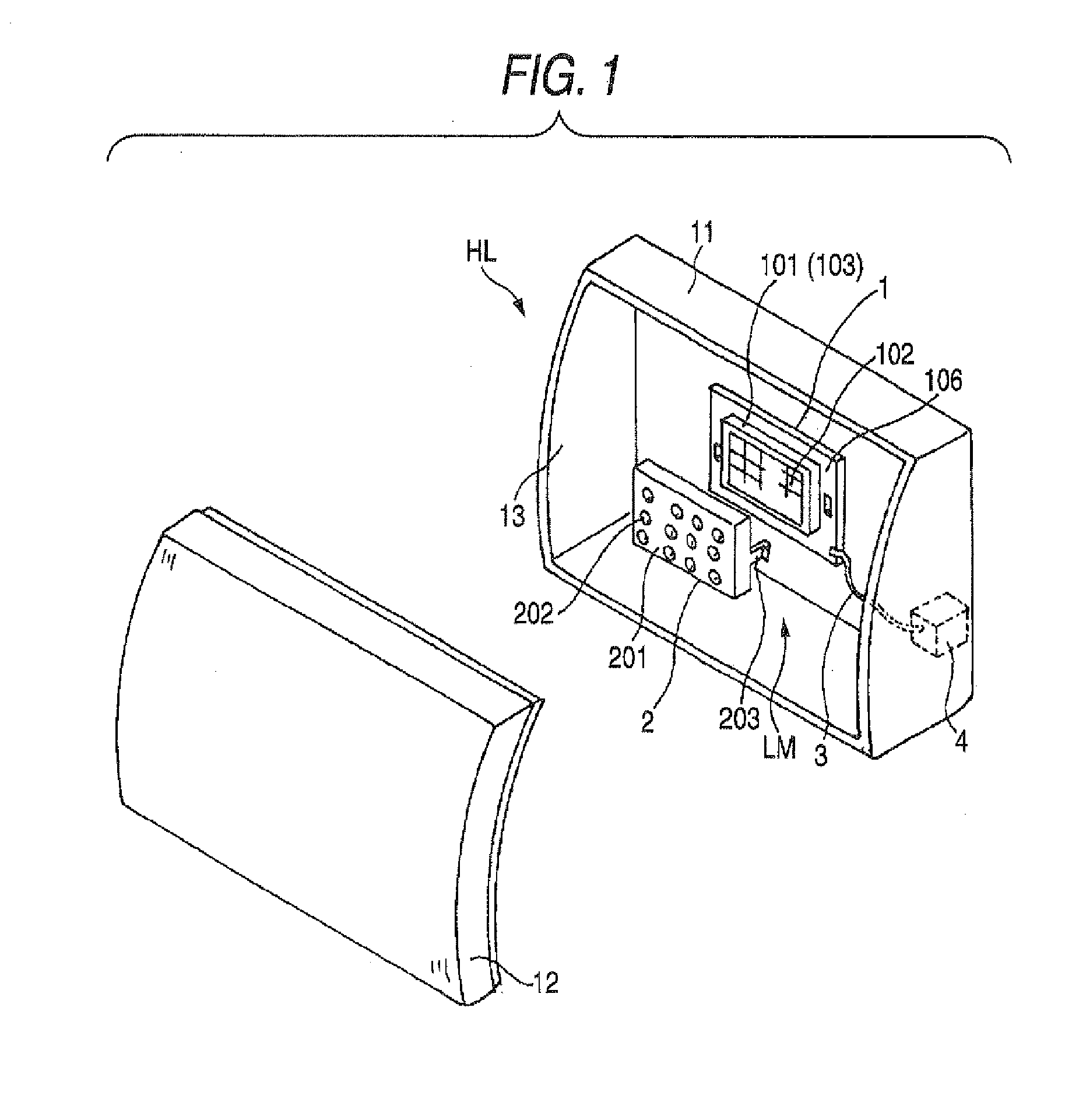
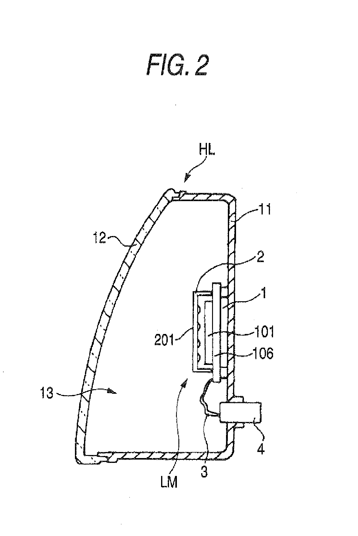
[0020]Next, exemplary embodiments of the present invention will be described with reference to the drawings. FIG. 1 is a partially exploded perspective view showing a schematic configuration of an exemplary embodiment in which the present invention is applied to a headlamp HL disposed in the right and left of the front of an automobile, and FIG. 2 is a longitudinal sectional view along an optical axis. A lamp chamber 13 is constructed of a shallow dish-shaped lamp body 11 with a required front shape and a transparent cover 12 attached to a front opening of this lamp body 11, and a light source part 1 and an optical member 2 are disposed inside this lamp chamber 13. In this exemplary embodiment, the light source part 1 and the optical member 2 are constructed as a lamp module LM. The lamp module LM is integrally provided with a lighting control circuit (not shown), and is constructed so that lighting of the lamp module LM is controlled based on a signal from an ECU (electronic contro...

second exemplary embodiment

[0030]FIG. 5 is an exploded perspective view showing a schematic configuration of a headlamp HL of another exemplary embodiment. This exemplary embodiment is constructed as a projector type lamp, and a lamp body 11A is formed in a cylindrical container shape and a light source part 1A is disposed in the bottom of the lamp body 11A. Also, a projection lens 12A with condensing properties as an optical member 2A is disposed in a front opening. Since a configuration of the light source part 1A is of a similar configuration as a light source part 1 of the first exemplary embodiment, the description is omitted. Also, the lens body 201 comprising the microlenses as shown in the first exemplary embodiment is not disposed integrally with respect to the light source part 1A and a lamp module is not constructed. Then, in the second exemplary embodiment, the projection lens 12A is constructed as an optical member according to exemplary embodiments of the present invention.

[0031]A mask 103 for c...


PUM


Abstract

A lamp module is constructed of a light source part made of a semiconductor light emitting element, and an optical member for distributing light emitted from the light source part. The light source part includes a surface-emitting laser element in which plural light emission parts are parallel arranged on a surface, a mask which is disposed on a surface of the surface-emitting laser element and includes plural mask openings for exposing the light emission parts, and fluorescent substances with which the mask openings are filled. By forming the light source part in a monolithic configuration, an array pitch of the plural light emission parts can be decreased, a light source can be miniaturized and also a lamp can be further miniaturized.

Description

[0001]This application claims priority from Japanese Patent Application No. 2006-177612, filed Jun. 28, 2606, in the Japanese Patent Office, to content of which is incorporated by reference in its entirety.TECHNICAL FIELD[0002]The present disclosure relates to a lamp for a vehicle using a semiconductor light emitting element such as a light emitting diode (LED) or a laser diode (LD) as a light source, and particularly, to a compact and lightweight lamp for a vehicle, capable of obtaining required luminous intensity and light distribution characteristics.RELATED ART[0003]In recent years, semiconductor light emitting elements such as an LED or an LD have been used as a light source used in an automobile lamp, and a part of the elements have been also used as a light source of a headlight (headlamp). For example, in Japanese Patent Unexamined Publication No. 2004-362840, a light source unit is constructed by arranging plural semiconductor light emitting chips on a front surface of a su...

Claims


Application Information

Patent Timeline
IPC IPC(8): F21S8/10H01L33/32H01L33/50H01L33/54H01L33/56H01L33/60
CPCF21K9/00F21V17/164F21S48/1163F21S48/1747F21S48/215F21Y2101/02F21Y2101/025H01S5/005H01S5/02228H01S5/02296H01S5/423H01L25/0753H01L33/60Y10S362/80H01L2924/0002F21S48/1154H01L2924/00F21Y2115/30F21S41/143F21S41/155F21S41/663F21S43/14F21S41/16F21S41/153F21Y2115/10F21V5/007H01S5/02234H01S5/02257F21S41/176H01S5/0087H01S5/18394F21Y2101/00
Inventor TAKEDA, HITOSHITOKIDA, TSUKASA
Owner KOITO MFG CO LTD
Why Eureka
Try Eureka