Apparatus and System for Recognizing Environment Surrounding Vehicle

a technology for recognizing objects and vehicles, applied in television systems, navigation instruments, instruments, etc., can solve the problems of difficult to predict a specific position on the screen, difficult to improve a recognition rate, and reduce false recognition, so as to improve the recognition rate of objects and accurate recognition of objects. , the effect of reducing false recognition

Inactive Publication Date: 2008-01-17
HITACHI LTD
View PDF5 Cites 65 Cited by
  • Summary
  • Abstract
  • Description
  • Claims
  • Application Information

AI Technical Summary

Benefits of technology

[0009] Luminance information of the image taken by the second camera, such as a camera or the like disposed forwardly of the vehicle, is used to predict possible changes to be made in luminance of the field of view of the rearwardly disposed first camera. Gain and exposure time of the rearwardly disposed first camera are then adjusted. Parameters (gain and exposure time) of the first camera are thereby adjusted even more quickly, so that even more accurate recognition of the object to be recognized can be achieved.
[0010] An improved recognition rate of the object to be recognized and reduced false recognition can be achieved as compared with the apparatus using only a single camera.

Problems solved by technology

The road surface marking appears from a lower end of a screen of an image taken by the camera, which makes it difficult to predict a specific position in the screen from which the road surface marking appears.
It is therefore an extremely short period of time for an object to be recognized to be acquired.
Accordingly, it is difficult to improve a recognition rate and reduce false recognition.
The two cameras are not thus utilized effectively.

Method used


Image

  • Apparatus and System for Recognizing Environment Surrounding Vehicle
  • Apparatus and System for Recognizing Environment Surrounding Vehicle
  • Apparatus and System for Recognizing Environment Surrounding Vehicle

Examples


first embodiment

[0066] A first embodiment will be described as applied to a system recognizing road surface markings by using images taken by a rear camera mounted in a vehicle.

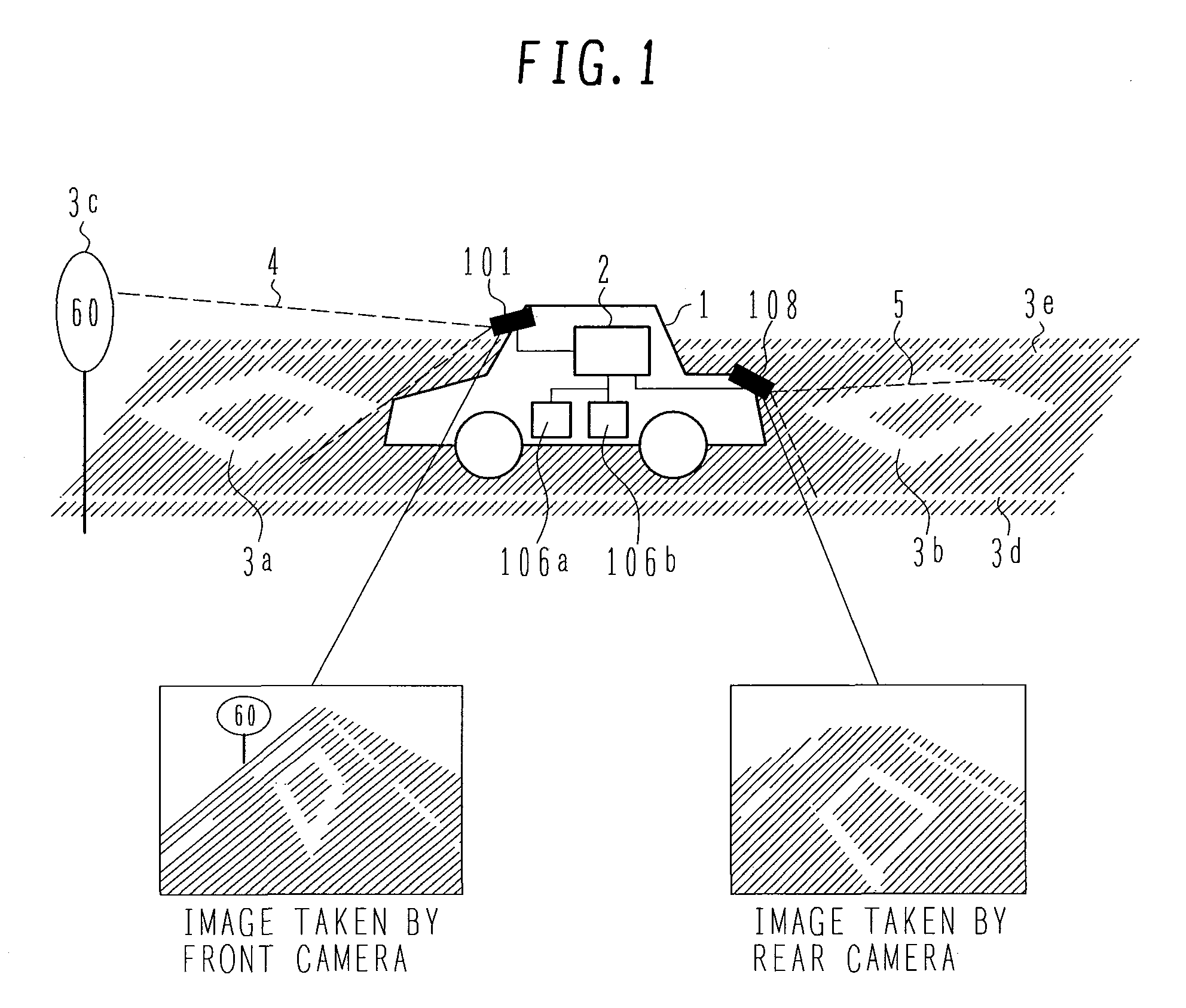
[0067]FIG. 1 is a view showing a system for recognizing an environment surrounding a vehicle according to the first embodiment. A vehicle 1 has a front camera 101 and a rear camera 108 mounted thereon. The front camera 101 takes an image of a view forward of the vehicle 1. The rear camera 108 takes an image of a view rearward of the vehicle 1. The front camera 101 is mounted such that a road surface falls within a field of view 4 of the front camera 101. The rear camera 108 is mounted such that the road surface falls within a field of view 5 of the rear camera 108.

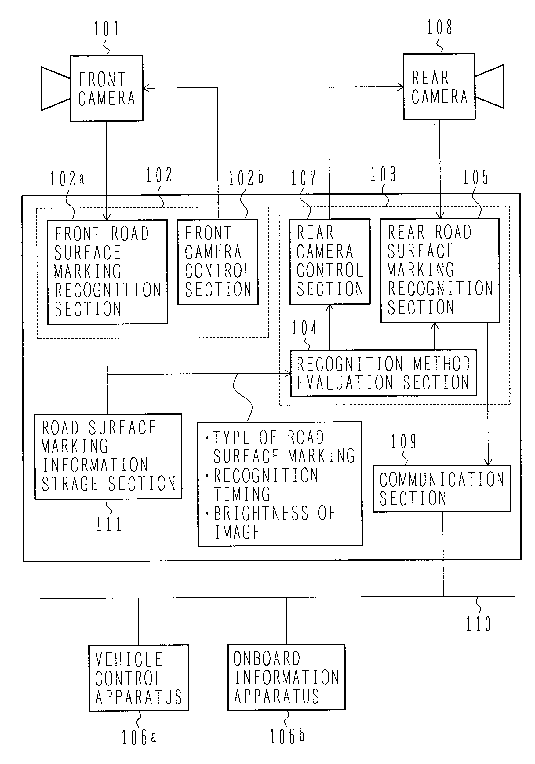
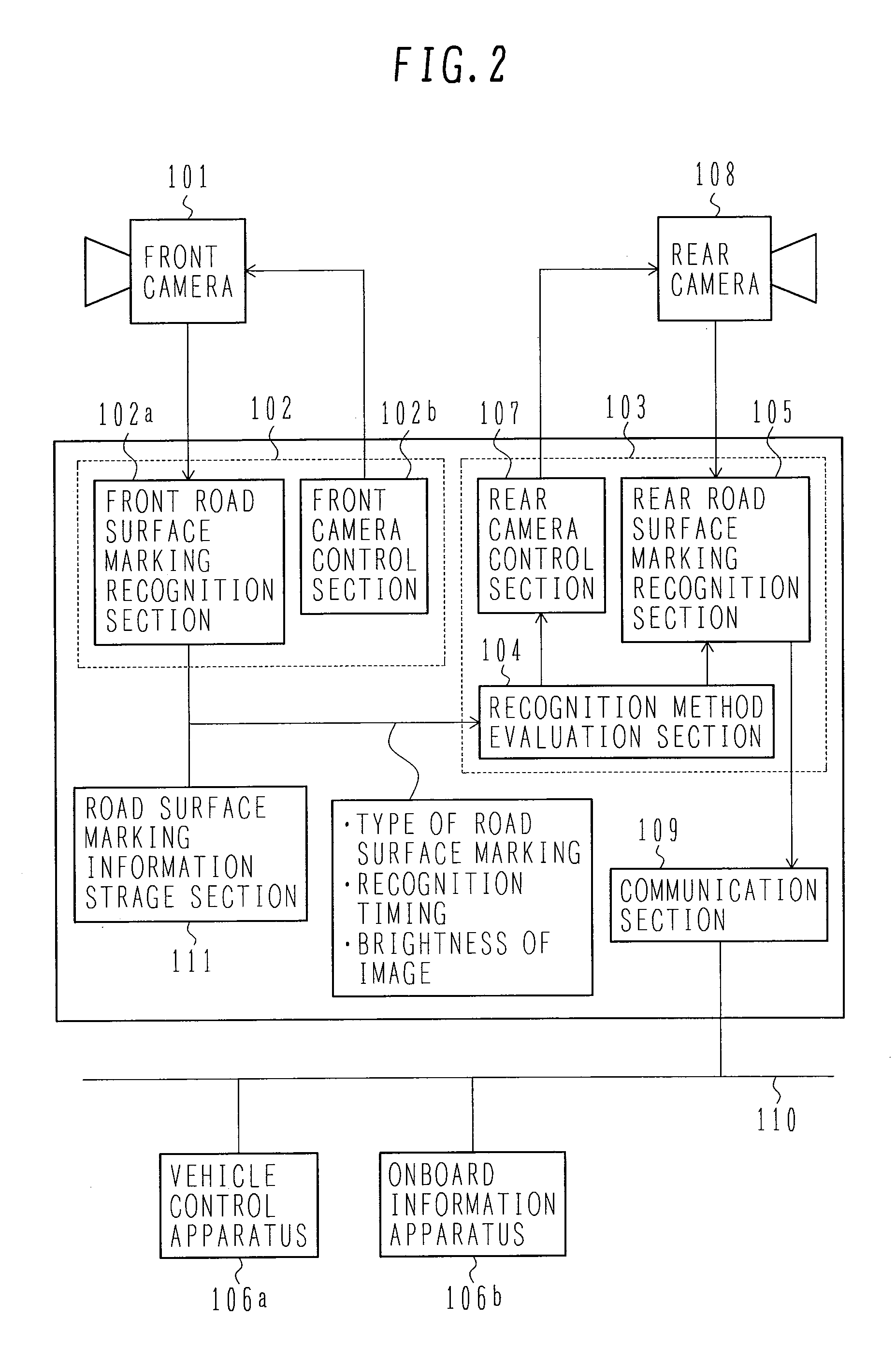
[0068] Image information captured by the front camera 101 is inputted to a surrounding environment recognition apparatus 2. The surrounding environment recognition apparatus 2 recognizes a road surface marking 3a forward of the vehicle 1 based on the image inform...

second embodiment

[0168]FIG. 48 shows a hardware block diagram of a system for recognizing an environment surrounding a vehicle according to a second embodiment. Major differences from the first embodiment described with reference to FIGS. 1 through 47 include the following. Specifically, a front camera image recognition unit 102 is disposed inside a front camera 101; and a rear camera image recognition unit 103 is disposed in another vehicle control function 2510a or onboard information function 2510b. Accordingly, the same processes for recognizing and evaluating the surrounding environment as those of the first embodiment apply unless otherwise noted. Differences from the first embodiment will be described below.

[0169] The front camera 101 includes a lens 2501, an imaging device (CCD) 2502, a CPU 2503, and a memory (not shown). The front camera 101 achieves the function of the front camera image recognition unit 102 using the CPU 2503 and the memory. A rear camera 108, on the other hand, includes...

third embodiment

[0173]FIG. 49 shows a hardware block diagram of a system for recognizing an environment surrounding a vehicle according to a third embodiment. Major differences from the first embodiment described with reference to FIGS. 1 through 47 include the following. Specifically, a front camera image recognition unit 102 is disposed inside a front camera 101; and a rear camera image recognition unit 103 is disposed inside a rear camera 108. Accordingly, the same processes for recognizing and evaluating the surrounding environment as those of the first embodiment apply unless otherwise noted. Differences from the first embodiment will be described below.

[0174] The front camera 101 shares the same arrangement with that of the second embodiment, except that the front camera 101 according to the third embodiment is connected to the rear camera 108 via a dedicated signal line 2609.

[0175] The rear camera 108 includes a lens 2504, an imaging device (CCD) 2505, a CPU 2608, and a memory (not shown)....


PUM


Abstract

In conventional systems using an onboard camera disposed rearward of a vehicle for recognizing an object surrounding the vehicle, the object is recognized by the camera disposed rearward of the vehicle. In the image recognized by the camera, a road surface marking taken by the camera appears at a lower end of a screen of the image, which makes it difficult to predict a specific position in the screen from which the road surface marking appears. Further, an angle of depression of the camera is large, and it is a short period of time to acquire the object. Therefore, it is difficult to improve a recognition rate and to reduce false recognition. Results of recognition (type, position, angle, recognition time) made by a camera disposed forward of the vehicle, are used to predict a specific timing and a specific position of a field of view of a camera disposed rearward of the vehicle, at which the object appears. Parameters of recognition logic of the rearwardly disposed camera and processing timing are then optimally adjusted. Further, luminance information of the image from the forwardly disposed camera is used to predict possible changes to be made in luminance of the field of view of the rearwardly disposed camera. Gain and exposure time of the rearwardly disposed camera are then adjusted.

Description

BACKGROUND OF THE INVENTION [0001] 1. Field of the Invention [0002] The specification relates to an apparatus and system that process images taken by a camera mounted in a vehicle and recognize road surface markings, traffic lights, signs, and the like on roads that surround the vehicle. [0003] 2. Description of the Related Art [0004] JP-A-3-220410 discloses an apparatus that processes images taken by a camera mounted in a vehicle and recognizes road surface markings. [0005] JP-A-6-206196 discloses an apparatus including cameras disposed forwardly and rearwardly of a vehicle. The apparatus detects contrast of an image taken by the forward camera and, if it is hard to obtain information on a forward image, uses information obtained by the rearward camera to recognize environment surrounding the vehicle. SUMMARY OF THE INVENTION [0006] The apparatus disclosed in JP-A-3-220410 has the onboard camera disposed rearwardly of the vehicle for recognizing the road surface markings. The road ...

Claims


Application Information

Patent Timeline
Patent Type & Authority Applications(United States)
IPC IPC(8): G06K9/00
CPCG06K9/00798G06V20/588
Inventor SHIMA, TAKESHIMURAMATSU, SHOJIOTSUKA, YUJIMACHII, KIMIYOSHIHIGUCHI, MIRAIMONJI, TATSUHIKOIRIE, KOTA
Owner HITACHI LTD
Why Eureka
Try Eureka