Image recording apparatus

Inactive Publication Date: 2008-01-17
BROTHER KOGYO KK
View PDF5 Cites 5 Cited by
  • Summary
  • Abstract
  • Description
  • Claims
  • Application Information

AI Technical Summary

Benefits of technology

[0011]In the image recording apparatus according to the present invention, the cover is provided so as to be pivotable between the open position and the closed position. According to pivoting of the cover, the linking member swings whereby the arm is pivoted. Thus, when the cover is positioned at the closed posi

Problems solved by technology

In other words, it is difficult to charge the recording sheets in a state in which the sheet-supply tray is attached to the device body because the sheet-feeding roller is in contact with the uppermost

Method used


Image

  • Image recording apparatus
  • Image recording apparatus
  • Image recording apparatus

Examples


Embodiment Construction

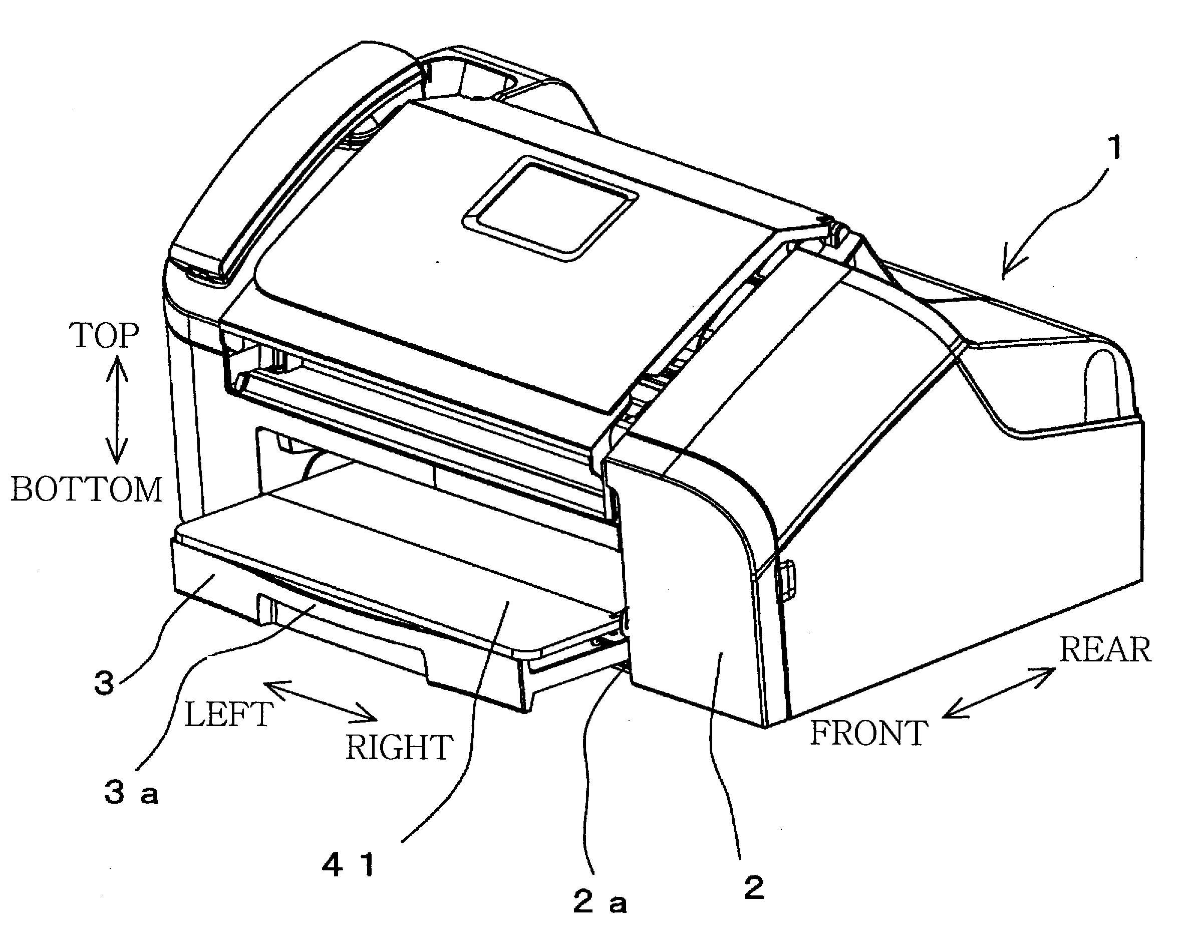
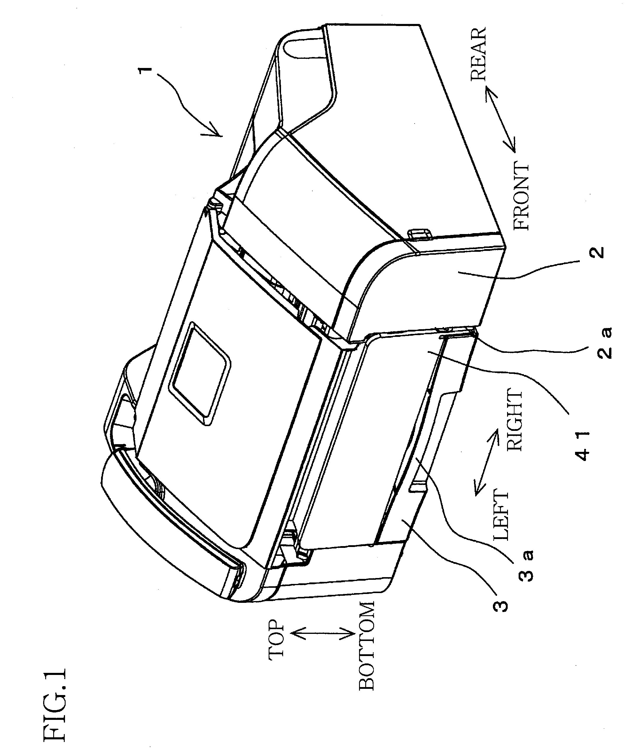
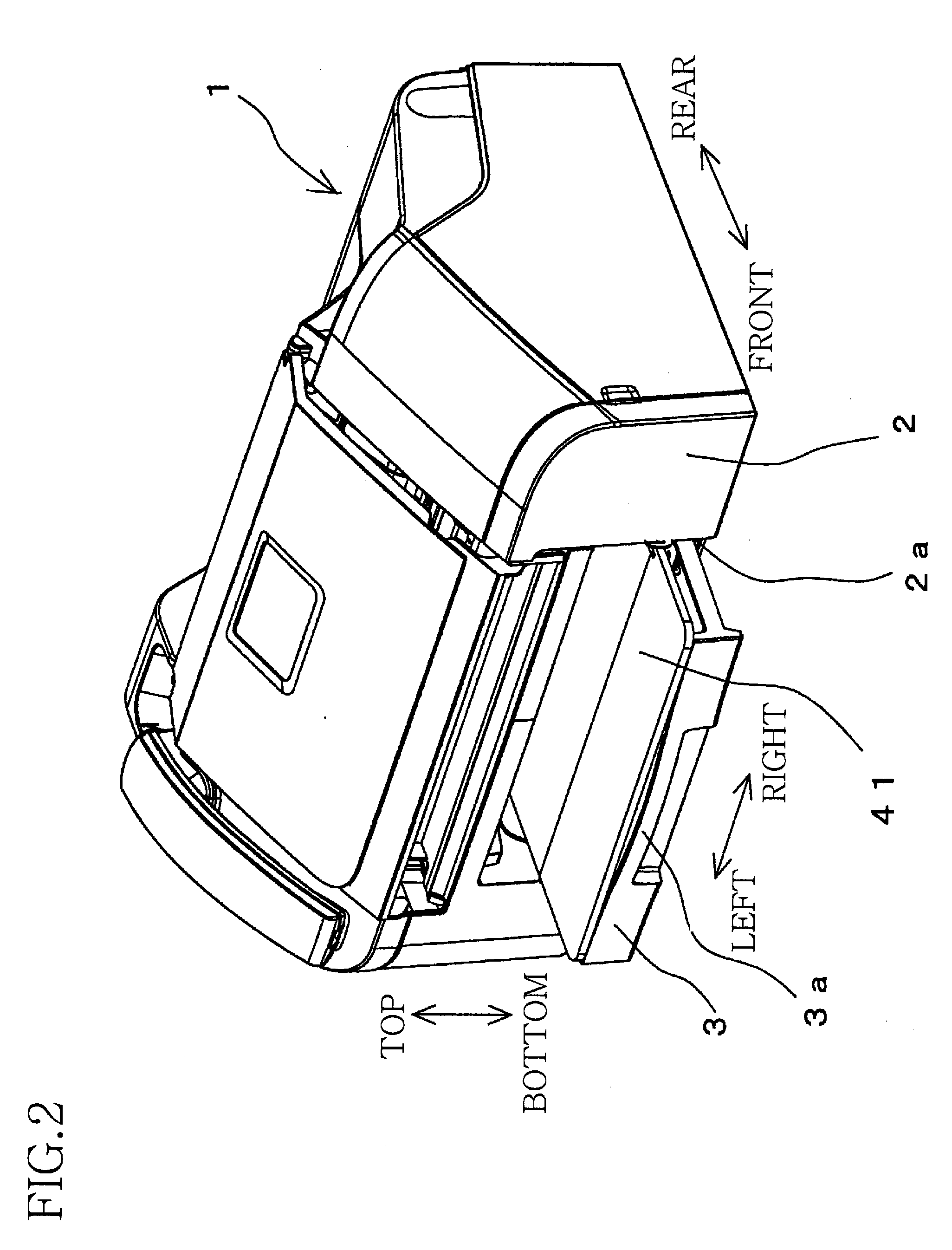
[0020]Hereinafter, there will be described a first preferred embodiment of the present invention by reference to the drawings. FIG. 1 is a perspective view showing an exterior configuration of an MFD (i.e., Multi Function Device) 1 including an image recording device 15 when a cover 41 is positioned at a closed position and a sheet-supply tray 3 is having a stay-in posture. FIG. 2 is a perspective view showing the exterior configuration of the MFD 1 when the cover 41 is positioned at an open position and the sheet-supply tray 3 is having a projecting posture. FIG. 3 is an enlarged cross-sectional side view of the MFD 1 in the state shown in FIG. 2. It is noted that, in the following description, there will be used terms “upward”, “downward”, “rightward”, “leftward”, “frontward” and “rearward” directions of the MFD 1 that are indicated by respective arrows “TOP”, “BOTTOM”, “RIGHT”, “LEFT”, “FRONT” and “REAR” in FIGS. 1 and 2. That is, the later-described sheet-supply tray 3 is provid...


PUM


Abstract

An image recording apparatus including: a body; a supply tray attached to the body for putting a recording sheet thereon; a recording mechanism provided in a middle of a feed path defined in the body for recording an image on the recording sheet; a feeding mechanism which has an arm pivotably supported at one of opposite ends thereof and a feeding roller rotatably provided in the other of the opposite ends of the arm, and which is configured such that the recording sheet is fed toward the recording mechanism by rotating of the feeding roller held in contact with the recording sheet; a discharge opening provided in the body for discharging the recording sheet therethrough; a cover supported by the body to be pivotable between an open position and a closed position; and a cover-arm interlock mechanism which permits the arm to pivot such that the feeding roller contacts the recording sheet when the cover is positioned at the open position, and which positions the arm such that the feeding roller is away from the recording sheet when the cover is positioned at the closed position.

Description

[0001]The present application is based on Japanese Patent Application No. 2006-181779 filed on Jun. 30, 2006, the contents of which are incorporated herein by reference.BACKGROUND OF THE INVENTION[0002]1. Field of the Invention[0003]The present invention relates to an image recording apparatus in which a recording sheet put on a supply tray is fed therefrom and an image is recorded on the same sheet.[0004]2. Discussion of Related Art[0005]Generally, in a conventional image recording apparatus, recording sheets put on a sheet-supply tray are fed into a feed path one by one. An image is recorded, by an image recording mechanism provided in the feed path, on a recording sheet that has been fed into the feed path. Then, the recording sheet (on which the image has been recorded) is discharged into a sheet-discharge tray.[0006]In a conventional image recording apparatus disclosed by Japanese Unexamined Patent Application Publication No. 11-5634, there is adopted a cassette-type sheet-supp...

Claims


Application Information

Patent Timeline
IPC IPC(8): G03G5/00
CPCB41J13/025B41J29/02B41J13/103
Inventor IZUCHI, MASATOSHI
Owner BROTHER KOGYO KK
Why Eureka
Try Eureka