Organic electroluminescent device using aryl amine derivative containing heterocycle

a technology of aryl amine and electroluminescent device, which is applied in the direction of organic semiconductor device, organic chemistry, natural mineral layered products, etc., can solve the problems of shortening the device life and the material described in patent document 8 is not satisfactory in both luminous efficiency and device li

Active Publication Date: 2008-01-17
IDEMITSU KOSAN CO LTD +1
View PDF17 Cites 568 Cited by
  • Summary
  • Abstract
  • Description
  • Claims
  • Application Information

AI Technical Summary

Benefits of technology

[0034] According to the technology of the invention, a low-voltage, high-efficiency, and long-lived an organic EL device can be realized by the used of a material with a specific structure.

Problems solved by technology

The compound increases luminous efficiency when used as a hole-transporting material, but has such a disadvantage that the driving voltage significantly increases which results in an extremely shortened device life.
The material described in Patent Document 8 is not satisfactory in respect both of luminous efficiency and device life.

Method used


Image

  • Organic electroluminescent device using aryl amine derivative containing heterocycle
  • Organic electroluminescent device using aryl amine derivative containing heterocycle
  • Organic electroluminescent device using aryl amine derivative containing heterocycle

Examples


example 1

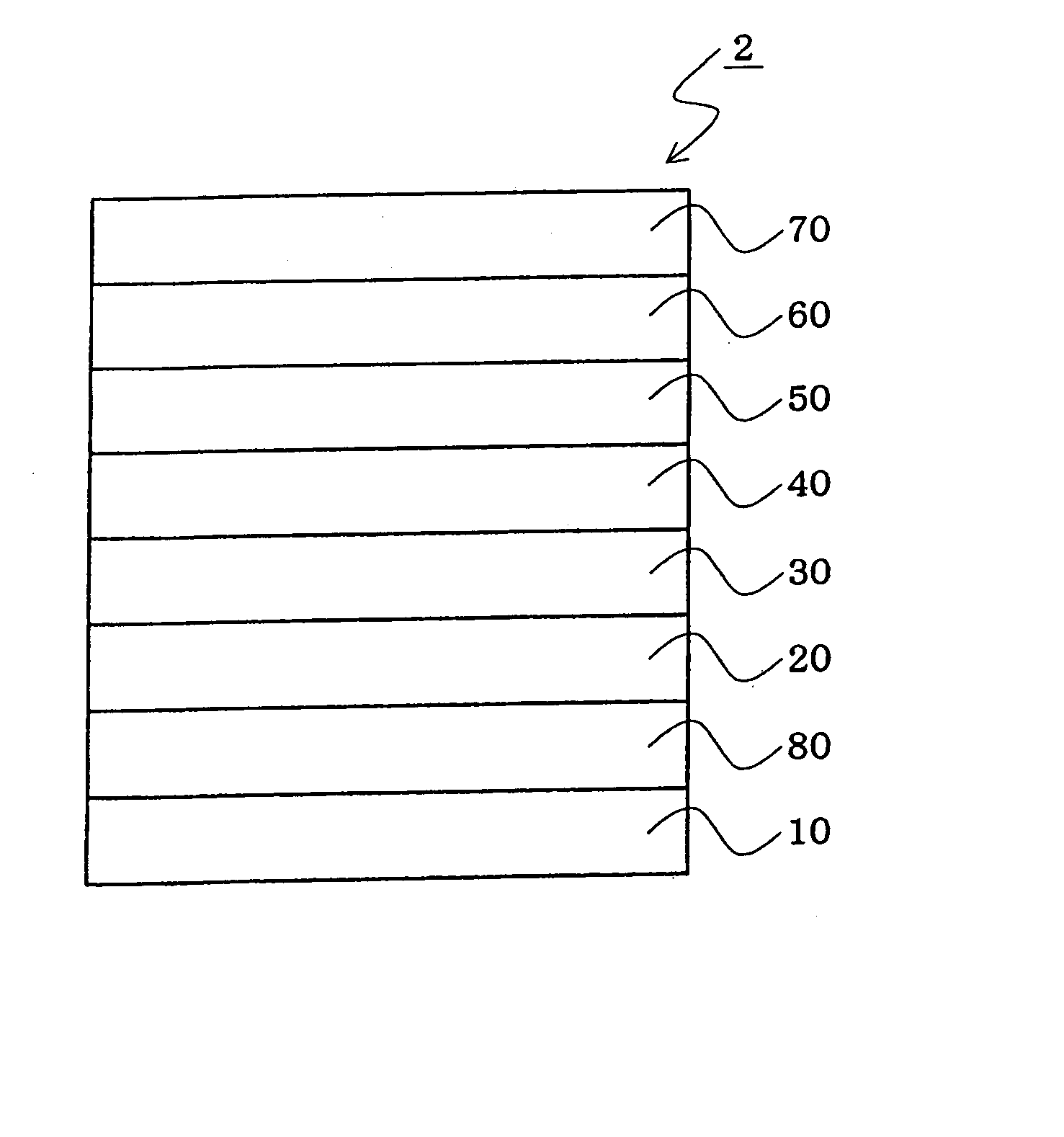
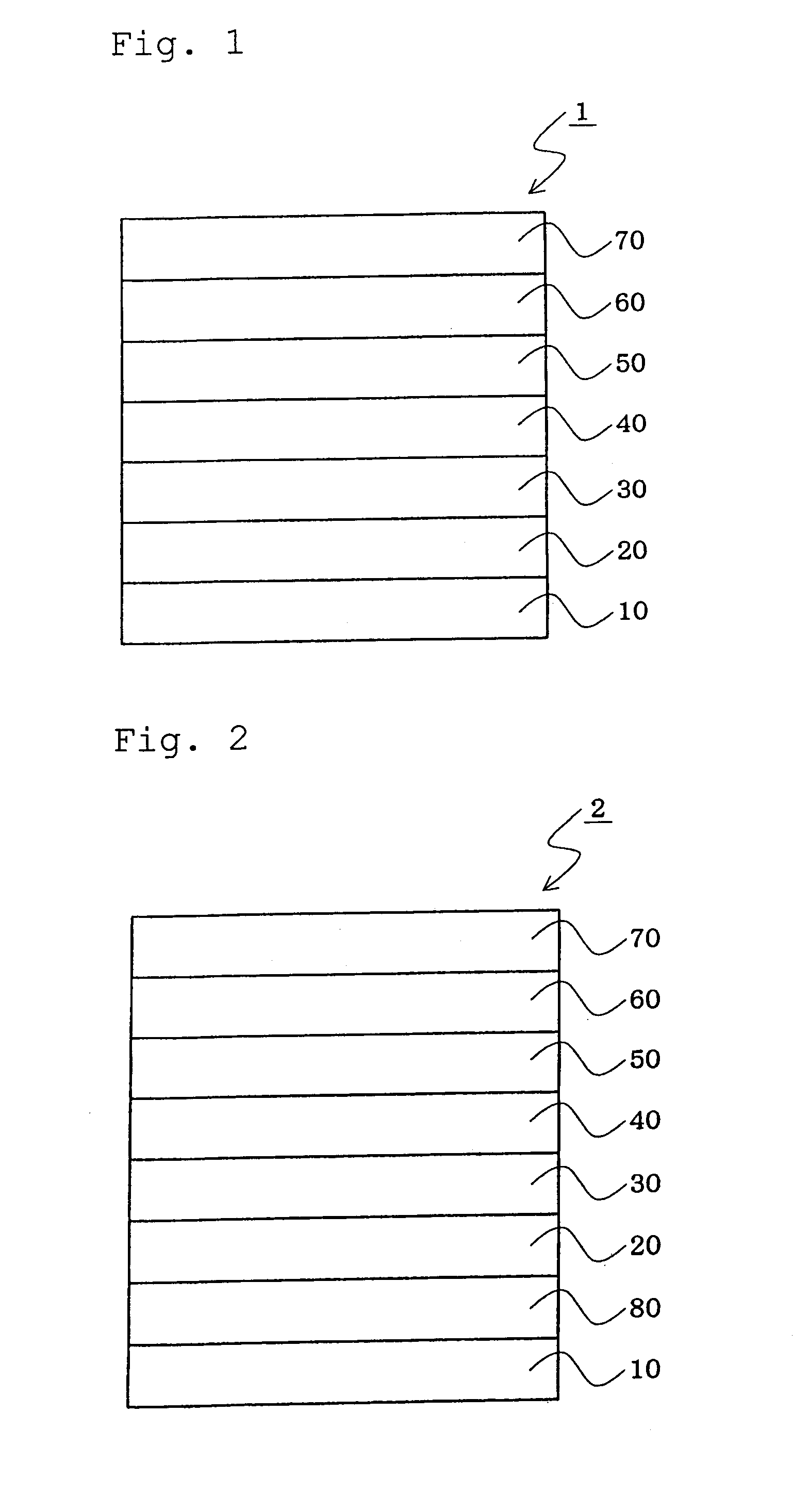
[0385] A glass substrate of 25 mm by 75 mm by 1.1 mm thick with an ITO transparent electrode (anode) (GEOMATEC CO., LTD.) was subjected to ultrasonic cleaning with isopropyl alcohol for 5 minutes, and cleaned with ultraviolet rays and ozone for 30 minutes. The resultant substrate with transparent electrode lines was mounted on a substrate holder in a vacuum deposition device. First, a film of the compound B-1 represented by the following formula was formed as the hole-injecting layer in a thickness of 60 nm so as to cover the transparent electrode on the surface where the transparent electrode lines were formed. Subsequently, a film of the compound A-10 represented by the following formula was formed on the B-1 film in a thickness of 20 nm as the hole-transporting layer.

[0386] On the A-10 film, a film of an anthracene derivative AN-1 and a styrylamine derivative D-1 represented by the following formulas (film thickness ratio: AN-1:D-1=40:2) was formed in a thickness of 40 nm to for...

example 2

[0388] An organic EL device was fabricated in the same manner as in Example 1, except that the compound A-2 represented by the following formula was used instead of the compound A-10 as the hole-transporting layer.

example 3

[0389] An organic EL device was fabricated in the same manner as in Example 1, except that the compound A-6 represented by the following formula was used instead of the compound A-10 as the hole-transporting layer.


PUM

PropertyMeasurementUnit
reduction potentialaaaaaaaaaa
transmittanceaaaaaaaaaa

Abstract

An organic electroluminescent device including: an anode, a cathode, an emitting layer formed of an organic compound and interposed between the cathode and the anode, and two or more layers provided in a hole-injecting/hole-transporting region between the anode and the emitting layer; of the layers which are provided in the hole-injecting/hole-transporting region, a layer which is in contact with the emitting layer containing a compound represented by the formula (1); and of the layers which are provided in the hole-injecting/hole-transporting region, a layer which is interposed between the anode and the layer which is in contact with the emitting layer containing an amine derivative represented by the formula (2).

Description

TECHNICAL FIELD [0001] The invention relates to an organic electroluminescent device using a heterocycle-containing arylamine derivative. BACKGROUND [0002] An organic electroluminescent device (hereinafter, “electroluminescent” is often abbreviated as “EL”) is a self-emission device by the use of the principle that a fluorescent compound emits light by the recombination energy of holes injected from an anode and electrons injected from a cathode when an electric field is impressed. [0003] Since C. W. Tang et al. of Eastman Kodak Co. reported a low-voltage driven organic EL device in the form of a stacked type device (Non-Patent Document 1), studies on organic EL devices wherein organic materials are used as the constituent materials has actively conducted. [0004] In the organic EL device reported by Tang et al., tris(8-hydroxyquinolinol)aluminum is used for an emitting layer, and a triphenyldiamine derivative is used for a hole-transporting layer. The advantages of the stack structu...

Claims


Application Information

Patent Timeline
Patent Type & Authority Applications(United States)
IPC IPC(8): B32B9/00
CPCC09K11/06H01L51/5088C09K2211/1011C09K2211/1014C09K2211/1029C09K2211/1044H01L51/0051H01L51/0052H01L51/006H01L51/0061H01L51/0068H01L51/0072H01L51/0081H01L51/5048H01L2251/308C09K2211/1007C07D209/86C09K11/025H10K85/611H10K85/615H10K85/636H10K85/633H10K85/655H10K85/324H10K85/6572H10K50/14H10K50/17H10K2102/103H10K85/342H10K85/626H10K50/11H10K50/15H10K50/81H10K50/82H10K85/622H10K2101/10C09K2211/185
Inventor KAWAMURA, MASAHIROKAMBE, EMIKONAKAMURA, AKIFUMIKIJIMA, YASUNORIYOSHINAGA, TADAHIKOMATSUNAMI, SHIGEYUKI
Owner IDEMITSU KOSAN CO LTD
Why Eureka
Try Eureka