Racking balls on a pool table

Inactive Publication Date: 2008-01-17
BURLOCK DENYM V +5
View PDF0 Cites 11 Cited by
  • Summary
  • Abstract
  • Description
  • Claims
  • Application Information

AI Technical Summary

Benefits of technology

[0005] According to the invention, pool balls falling into the pockets of a pool table during a game are fed through primary conduits below the table and then passed one at a time through the field of view of a camera which identifies the colour and / or markings on the ball and forwards each ball through an appropriate secondary conduit to a rack located in a receiving position adjacent one end of the table. The rack is mounted on a carriage pivotally secured to the table at one end thereof so that, when the rack is full, the carriage can be pivoted from the receiving position to a discharge position over the table so that the balls can then be discharged from the rack in the correct formation on the table. Releasable retainers are provided to retain the balls in the rack during the pivoting movement and until the rack is in position over the table.

Problems solved by technology

However, this manual procedure is somewhat time consuming and tedious.

Method used


Image

  • Racking balls on a pool table
  • Racking balls on a pool table
  • Racking balls on a pool table

Examples


Embodiment Construction

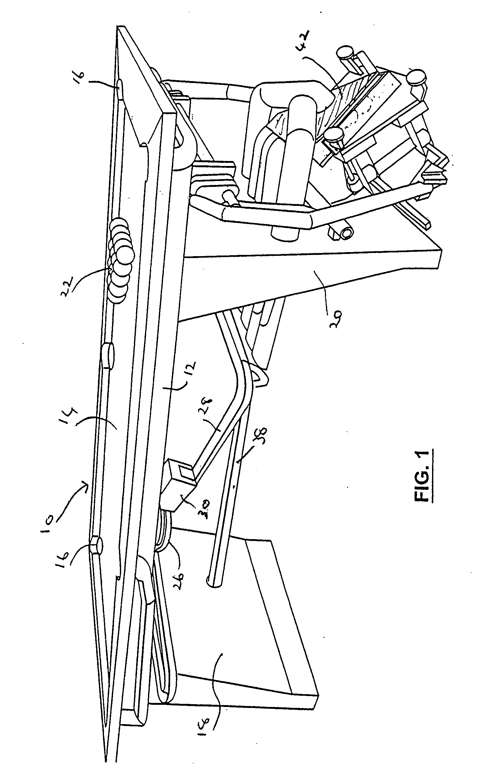
[0028] Referring to the drawings, FIG. 1 shows a pool table 10 has an upper portion 12 with a playing surface 14 and pockets 16. The upper portion 12 is supported by end supports 18, 20. Pool balls 22 are shown on the playing surface 14 in the conventional starting position.

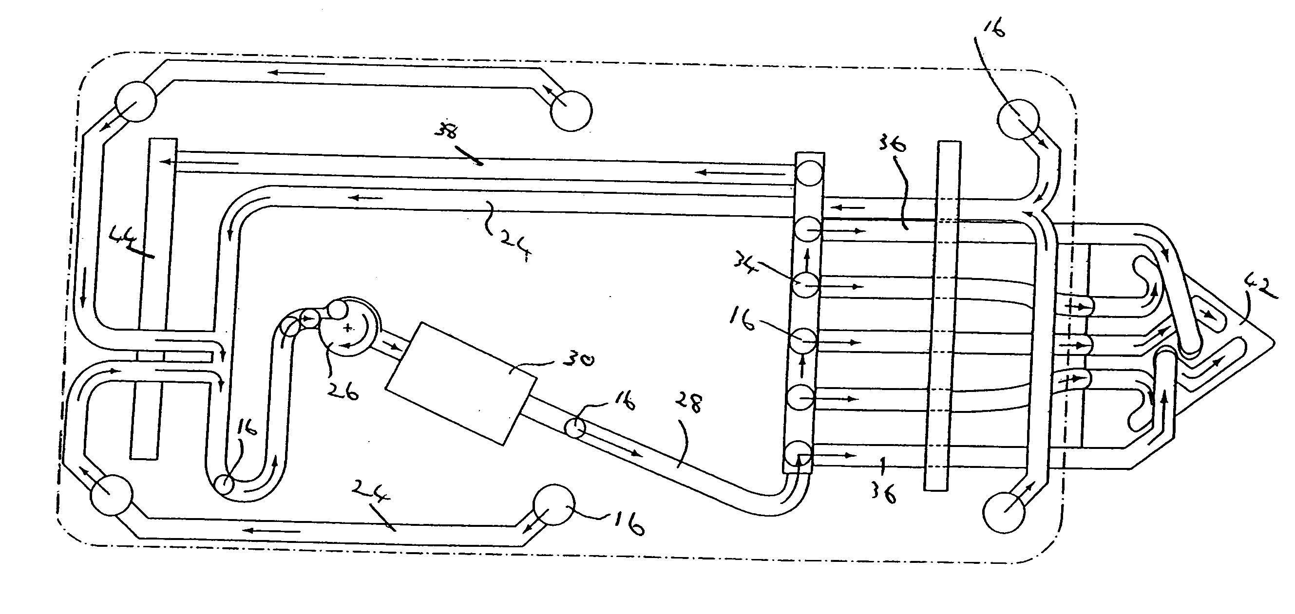
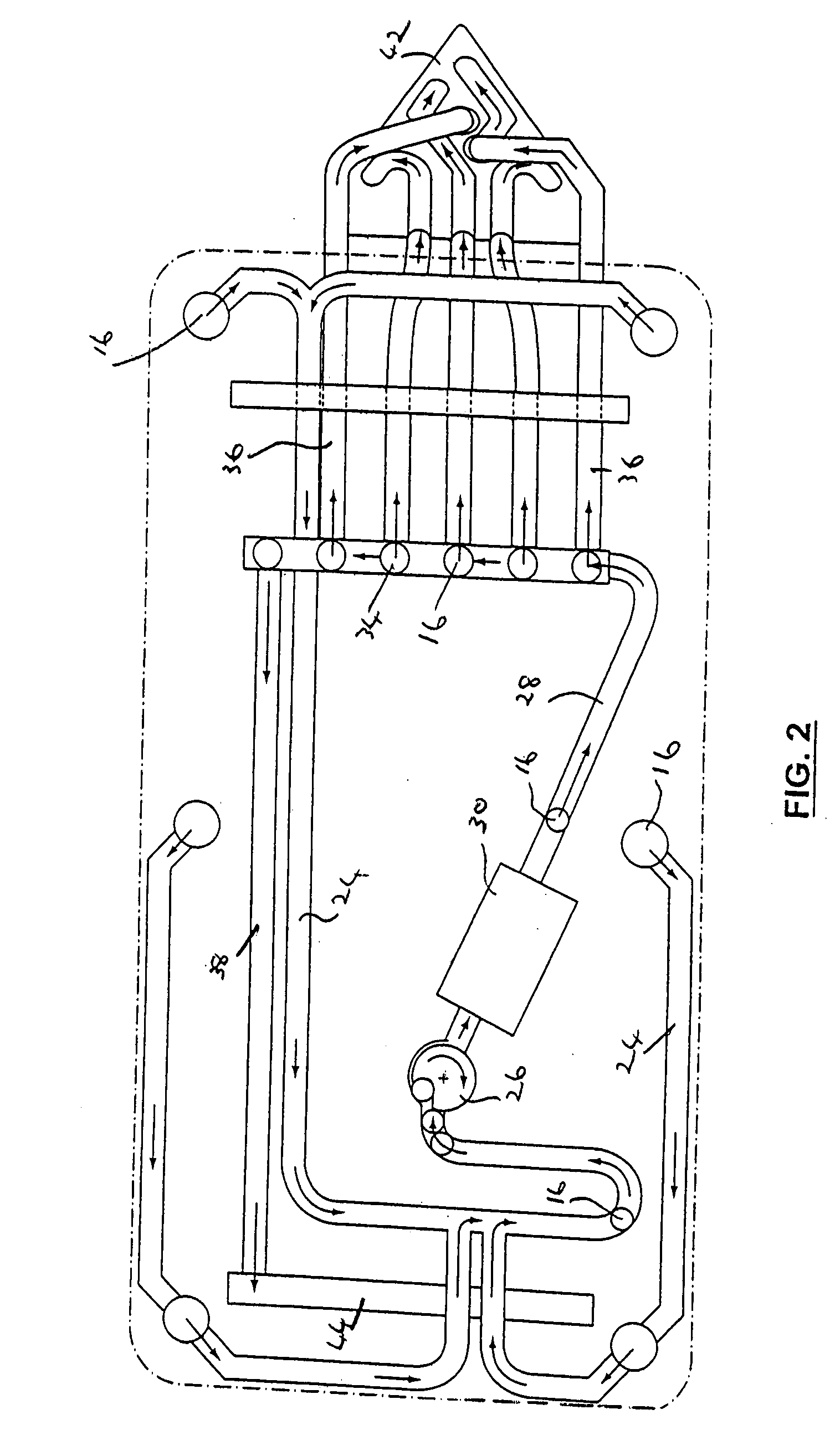
[0029] In accordance with the invention and referring now also to FIGS. 2 to 4, primary conduits 24 extend below the table from each pocket 16 to a carousel 12 which feeds the balls 16 one at a time along a conduit 28 past the field of view of a camera 30. As shown in FIGS. 5a and 5b, mirrors 32 are positioned to provide the camera with 3 images of each ball 16 from different angles. The camera 30 is programmed to distinguish between the different kinds of balls 16 downstream of the camera 30, a conduit 28 has a series of longitudinally spaced trap doors 34, see FIGS. 6 and 7. As shown in FIGS. 6 and 7, the trap doors 34 are pivotally mounted portions of the conduit 28. Each trap door 34 has an upper position al...


PUM


Abstract

Pool balls falling into the pockets of a pool table during a game are fed through primary conduits below the table and then passed one at a time through the field of view of a camera which identifies the color and / or markings on the ball and forwards each ball through an appropriate secondary conduit to a rack located in a receiving position adjacent one end of the table. The rack is mounted on a carriage pivotally secured to the table at one end thereof so that, when the rack is full, the carriage can be pivoted from the receiving position to a discharge position over the table so that the balls can then be discharged from the rack in the correct formation on the table. Releasable retainers are provided to retain the balls in the rack during the pivoting movement and until the rack is in position over the table.

Description

RELATED APPLICATION [0001] This application claims priority from U.S. Provisional Patent Application 60 / 794,138 filed Apr. 24, 2006.FIELD OF INVENTION [0002] This invention relates to racking balls on a pool table. BACKGROUND OF THE INVENTION [0003] As is well known, it is conventional to start a game of pool by arranging the balls in a specific triangular formation on a pool table. A triangular frame known as a rack is used to enable the balls to be manually placed in the required formation. However, this manual procedure is somewhat time consuming and tedious. [0004] It is therefore an object of the invention to provide apparatus for racking balls on a pool table. SUMMARY OF THE INVENTION [0005] According to the invention, pool balls falling into the pockets of a pool table during a game are fed through primary conduits below the table and then passed one at a time through the field of view of a camera which identifies the colour and / or markings on the ball and forwards each ball ...

Claims


Application Information

Patent Timeline
IPC IPC(8): A63D15/00
CPCA63D15/005
Inventor BURLOCK, DENYM V.KILFOIL, MARKFLETCHER, GEOFFRAIDAN, RAWADLATIMER, JOHNSCHAEFER, DANIEL
Owner BURLOCK DENYM V
Why Eureka
Try Eureka