
Circuit arrangement and method for controlling at least one actuator in a motor vehicle

Inactive Publication Date: 2008-01-17
ATMEL AUTOMOTIVE
View PDF7 Cites 7 Cited by
  • Summary
  • Abstract
  • Description
  • Claims
  • Application Information

AI Technical Summary

Benefits of technology

[0008] It is therefore an object of the present invention to provide a circuit arrangement, simple and cost-effective to implement, which drives the at least one actuator reliably and safely also when the microcontroller or microprocessor is not in the normal, actuator-controlling operating mode, but, for example, performs a self-test or receives a new program code for improved actuator control. It is furthermore the object of the invention to provide a corresponding method.
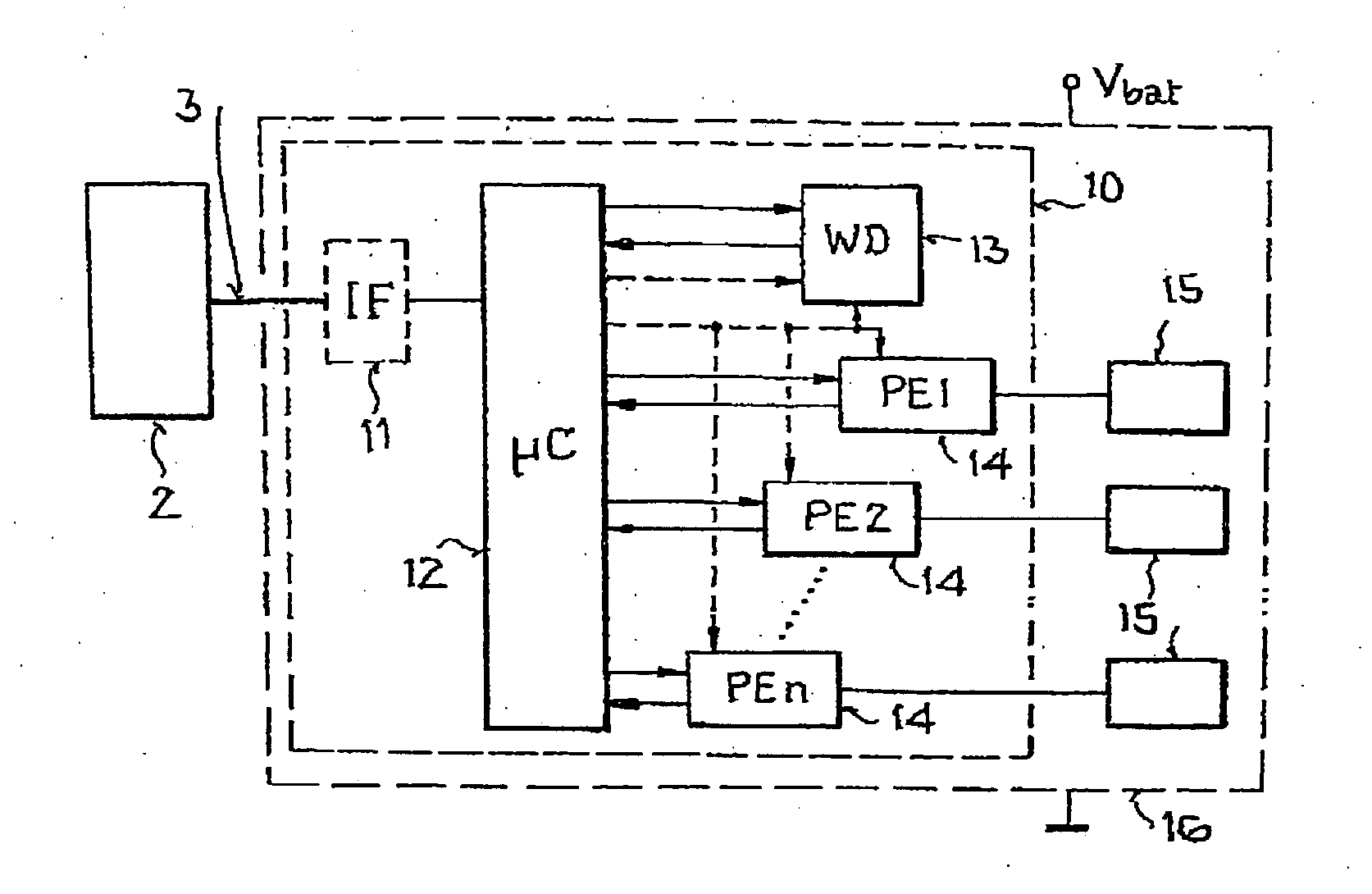
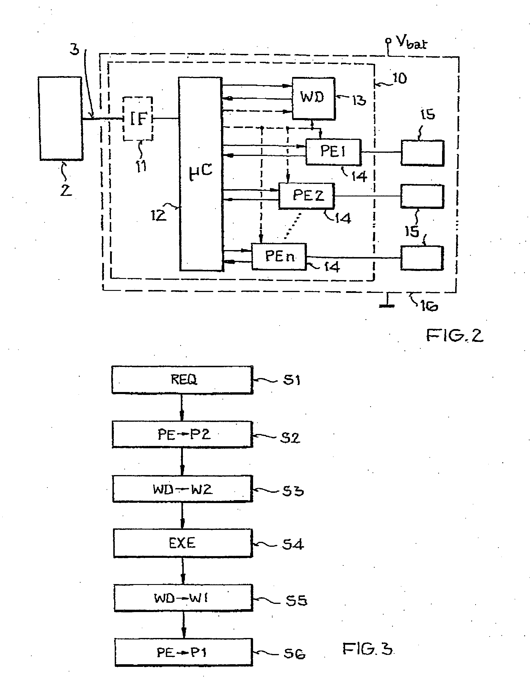
[0013] In an embodiment of the circuit arrangement and the method, the peripheral unit is changed to the second operating mode P2 at the latest when, preferably before, the watchdog circuit is changed to or is in the reduced activity operating mode W2. An especially safe and reliable actuator control is achieved in this way. Changing the peripheral unit to mode P2 before switching of the watchdog circuit makes it possible to take into account the time interval required at most by the actuator to achieve the safe state, so that the actuator reaches the safe state substantially when the watchdog circuit is switched to or is in mode W2.
[0015] In an embodiment of the circuit arrangement, the microcontroller is designed to change the peripheral unit from the first to the second and / or from the second to the first operating mode. This type of circuit arrangement is simple and cost-effective to implement.
[0016] In another embodiment of the circuit arrangement and the method, a new program code for the microcontroller is stored only when the watchdog circuit is in the reduced activity operating mode W2, and / or a microcontroller self-test is performed only when the watchdog circuit is in the reduced activity operating mode W2. In this way, it is advantageously assured that a download of a program code and / or a self-test can be accomplished without the risk of an erroneous driving of the actuator.
[0017] In another embodiment of the circuit arrangement and the method, the peripheral unit reacts exclusively to precisely one predefined command when it is in the second operating mode P2, and changes to the first operating mode P1 when it receives the predefined command. Especially safe and reliable actuator control is achieved in this way in which control errors are essentially eliminated.

Problems solved by technology

It is a disadvantage here that it is not possible without additional costly measures, e.g., to perform a microprocessor self-test or to receive a new program code for the microprocessor and to store it in a nonvolatile memory, because faulty triggering of the ignition end stages by the microprocessor and thereby an unintentional actuation of airbags, seat belt retractors, etc., are not systematically ruled out.

Method used


Image

  • Circuit arrangement and method for controlling at least one actuator in a motor vehicle
  • Circuit arrangement and method for controlling at least one actuator in a motor vehicle
  • Circuit arrangement and method for controlling at least one actuator in a motor vehicle

Examples


Embodiment Construction

[0023] In the figures, the same and functionally identical elements and signals, if not specified otherwise, are provided with the same reference characters.

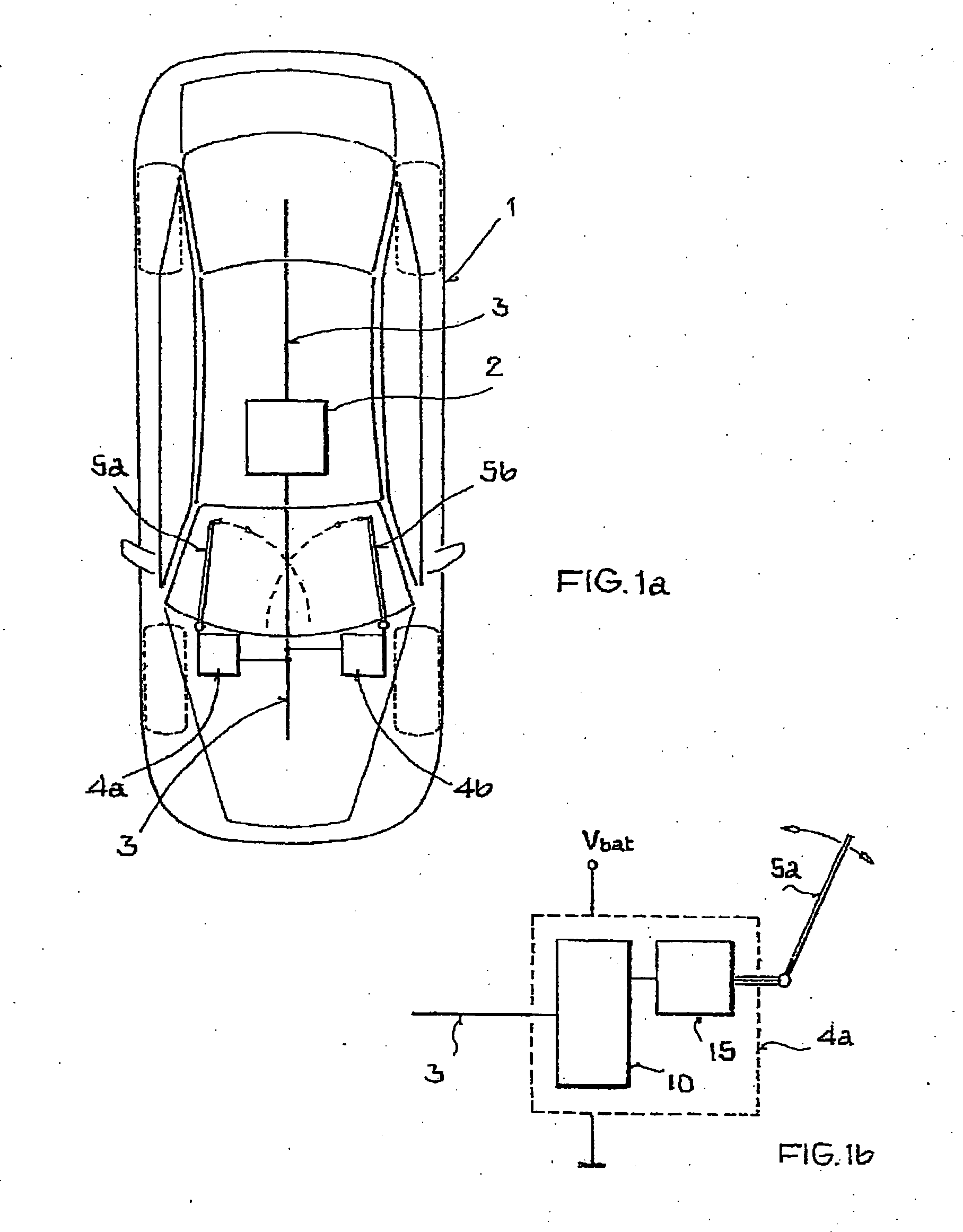
[0024]FIG. 1 shows a vehicle with a circuit arrangement of the invention.

[0025] According to the top plan view in FIG. 1a, motor vehicle 1 has a central control device 2 with a higher-order control computer which is connected by a serial control bus 3 to a plurality of vehicle components. The vehicle components controlled by the control computer are, for example, the depicted subassemblies (control devices) 4a, 4b for controlling the front windshield wipers 5a, 5b or other subassemblies for controlling headlights, seats, turbochargers, valves, etc., which are built at very different locations into motor vehicle 1. Many of these vehicle components have one or more actuators (also called control or positioning elements), which convert electrical energy into other forms of energy, such as, e.g., kinetic, potential, magnetic, and ...


PUM


Abstract

A circuit arrangement is provided for controlling at least one actuator in a motor vehicle, comprising a microcontroller, a watchdog circuit with an active operating mode for monitoring the functionality of the microcontroller and a reduced activity operating mode, and with at least one microcontroller-controlled peripheral unit with a first operating mode for controlling at least one actuator. According to the invention, the peripheral unit has a second operating mode and is designed to change the actuator to a safe mode and / or to keep it in this mode when the peripheral unit is in the second operating mode, and the circuit arrangement is designed to operate the peripheral unit in the second operating mode at least whenever the watchdog circuit is in the reduced activity operating mode. The invention relates furthermore to a corresponding method for controlling at least one actuator in a motor vehicle.

Description

[0001] This nonprovisional application claims priority to German Patent Application No. DE 102006029514, which was filed in Germany on Jun. 27, 2006, and to U.S. Provisional Application No. 60 / 819,385, which was filed on Jul. 10, 2006, and which are both herein incorporated by reference.BACKGROUND OF THE INVENTION [0002] 1. Field of the Invention [0003] The present invention relates to a circuit arrangement and a method for controlling at least one actuator in a motor vehicle. [0004] 2. Description of the Background Art [0005] The invention falls within the field of the control of actuators, such as, e.g., electric motors, electromagnets, and heating wires, which are built in many cases at very different locations into modern motor vehicles. Such actuators, often also called control or positioning elements, are used, for example, to drive windshield wipers or to set headlights, seats, thermostatic valves, throttle valves, turbochargers, etc. [0006] DE 102 55 430 A1 discloses a circu...

Claims


Application Information

Patent Timeline
IPC IPC(8): G05B11/01
CPCB60R2021/01068B60W50/00B60W50/0098G06F11/0757G05B2219/24125G05B2219/25158G05B9/02
Inventor PANNWITZ, AXEL
Owner ATMEL AUTOMOTIVE
Learn More