
Circuit arrangement for signal pick-up and signal generation and method for operating this circuit arrangement

a circuit arrangement and signal technology, applied in the field of circuit arrangement for signal pickup and signal generation, can solve the problems of large computing power of the microcontroller for implementing complex functionalities, high cost of more complex timer modules, and inability to implement complex applications in a large amount of software interaction, etc., to achieve simple and cost-effective implementation, high scalability, and high scalability

Active Publication Date: 2014-06-10
ROBERT BOSCH GMBH
View PDF14 Cites 0 Cited by
  • Summary
  • Abstract
  • Description
  • Claims
  • Application Information

AI Technical Summary

Benefits of technology

The invention is a circuit that allows for picking up and generating signals in a way that can be easily scaled, adapted to different communications needs, and processed quickly. It is also simple and inexpensive to implement.

Problems solved by technology

Using these modules, only limited timer functions are able to be produced on few I / O pins, which, it is true, does make the controllers cost-effective, but requires much software interaction in order to implement complex applications.
Because of their limited functionalities, the simpler timer modules are cost-effective to implement, but they do require a great deal of computing power of the microcontroller for implementing complex functionalities.
On the other hand, the more complex timer modules are costly, and are scalable only in limited fashion.
This may lead to some resources not being used to capacity.
This implementation, however, requires very many logic resources.

Method used


Image

  • Circuit arrangement for signal pick-up and signal generation and method for operating this circuit arrangement
  • Circuit arrangement for signal pick-up and signal generation and method for operating this circuit arrangement
  • Circuit arrangement for signal pick-up and signal generation and method for operating this circuit arrangement

Examples


Embodiment Construction

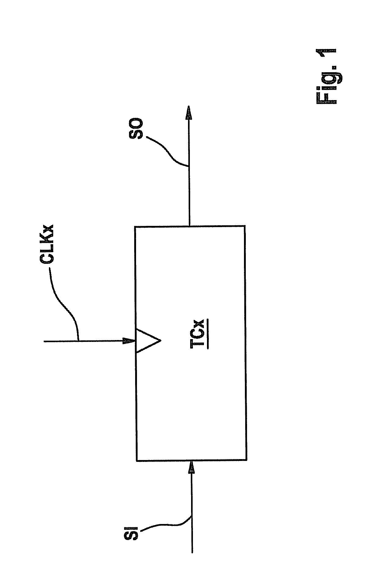
[0027]FIG. 1 shows a time control module TCx (time controller) to explain the principle of the time-dependent processing and the generating of signals in the related art. In module TCx, in this instance, one or more input signals SI (signal in) are picked up and / or counted as a function of a clock pulse CLKx (clock), and as a function of that, one or more output signals SO (signal out) are generated.

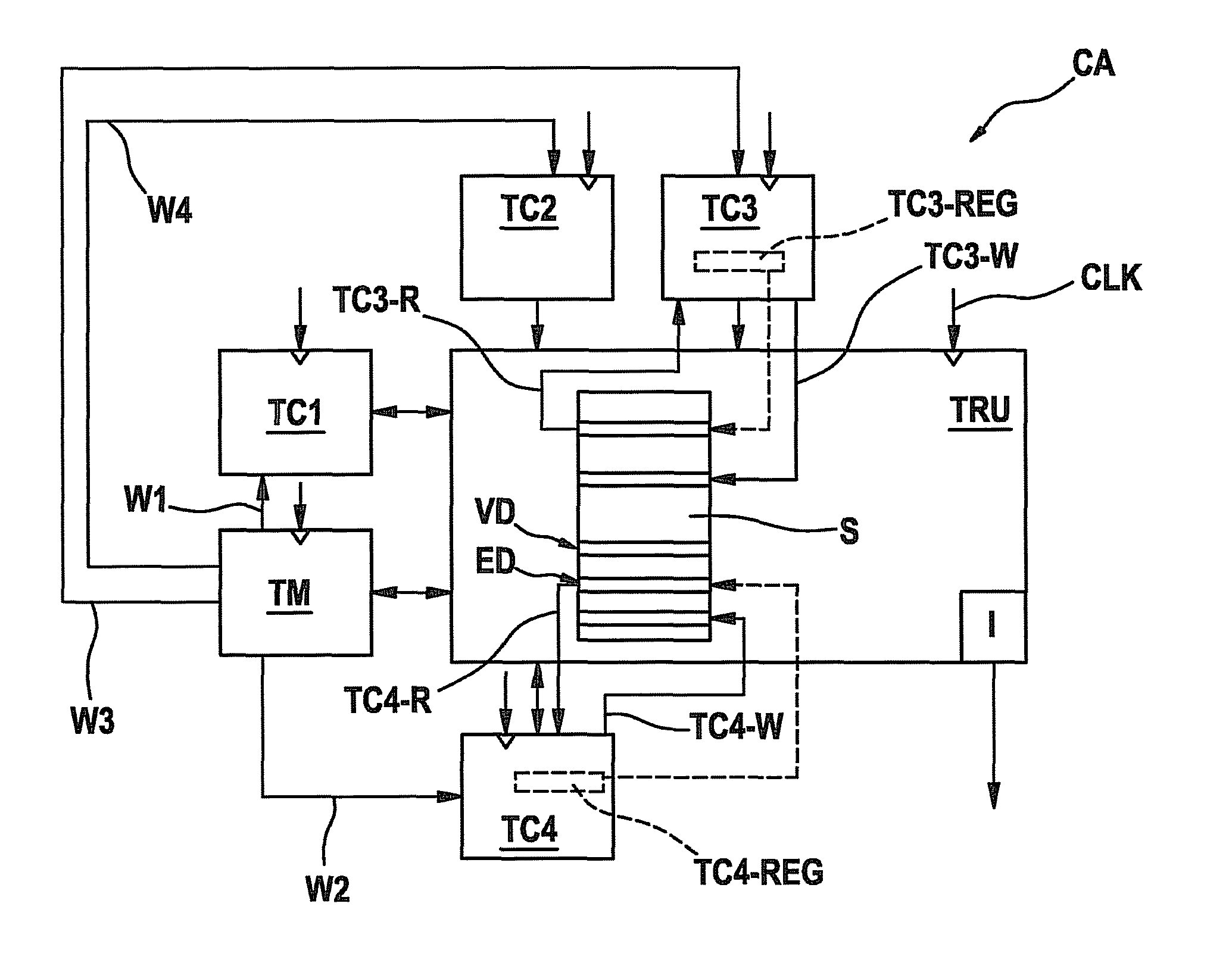
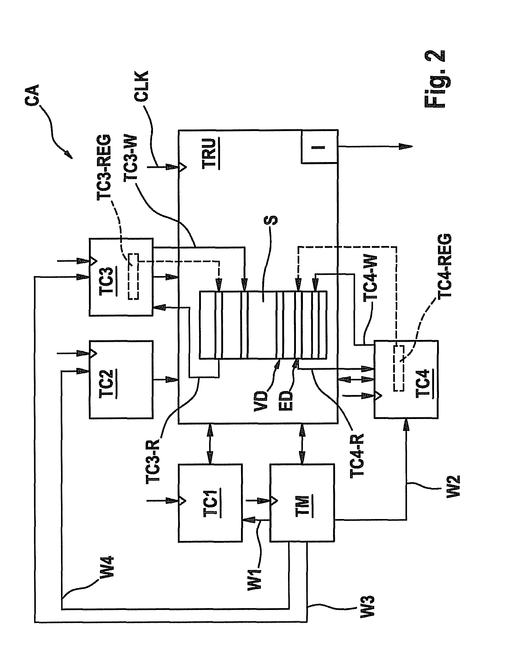
[0028]FIG. 2 shows a block diagram of a first specific embodiment of the circuit arrangement CA (circuit arrangement) to explain its manner of functioning. One time routing unit (TRU) enables an efficient signal evaluation and / or generation based on one or more time bases TM (timer module), as shown in FIG. 1. Time bases TM are connected via fixed lines W1 . . . W4 (wiring) to time control modules TC1 . . . TC4 (time controller). In a time control module TC1 . . . TC4, the signal multiplexing described in FIG. 1 is undertaken. One or more time control units may also be interconnected in ...


PUM


Abstract

A circuit arrangement for signal pick-up and signal generation and a method for operating this circuit arrangement. The circuit has at least one timer module for providing a time basis to a plurality of time control modules connected to it, and has a time routing unit, which is connected to it for the interconnection of the named modules and their signals.

Description

FIELD OF THE INVENTION[0001]The present invention relates to a circuit arrangement for signal pick-up and signal generation, as well as a method for operating this circuit arrangement.BACKGROUND INFORMATION[0002]Such circuits may be implemented, for example, as timer modules in microcontrollers. The modules are developed as individual components, in this instance, or as peripheral modules of the controller, which provide more or less powerful functions for signal pick-up and signal generation in dependence, as a function of time, of one or more clock pulses.[0003]At the present time, different concepts for implementing timers are being used. In this connection, one may basically distinguish between complex and less complex implementations.[0004]In the category of less complex timers, one might mention MTU (multi-function timer pulse unit) of Renesas™ controllers SH7741-HD6417641. It supplies the user with 5 time control units that are connected to 16 I / O pins. Time control units sho...

Claims


Application Information

Patent Timeline
Patent Type & Authority Patents(United States)
IPC IPC(8): H04L12/50G06F13/14H04Q11/00
CPCG06F1/04
Inventor SCHMITT, STEPHENHANISCH, JUERGEN
Owner ROBERT BOSCH GMBH
Learn More