Linearization method and amplifier arrangement

a linearization method and amplifier technology, applied in amplifiers, gain control, electrical equipment, etc., can solve the problems of not being optically suitable for use in amplifiers amplifying high frequency signals, linearization methods based on feedback are not particularly suitable for effective amplifier stages, and the solution disclosed is relatively complex to implement, so as to reduce the arrangement is simple and cost-effective to implement, and the effect of reducing the heat produced by the amplifier

Inactive Publication Date: 2005-11-29
ELEKTROBIT WIRELESS COMM OY
View PDF16 Cites 0 Cited by
  • Summary
  • Abstract
  • Description
  • Claims
  • Application Information

AI Technical Summary

Benefits of technology

[0014]The method and arrangement of the invention provide several advantages. The arrangement is suitable for linearizing an amplifier amplifying signals with variable envelopes in particular. The linearization method enables more low-power amplifiers to be used, which means that the waste heat produced by the amplifier can be reduced. The method is suitable for use in amplifiers amplifying e.g. OFDM signals, whose levels vary considerably.
[0015]The arrangement is suitable both for narrowband and broadband modulated signals. In addition, the arrangement remains stable within a wide temperature range, which reduces the heat produced by the amplifier. The arrangement is simple and cost-effective to implement. The arrangement can thus be readily applied e.g. to systems comprising several amplifiers.

Problems solved by technology

The solution disclosed is relatively complex to implement.
The linearization methods based on feedback are not particularly suitable for use in effective amplifier stages.
The linearization methods are not optically suitable for use in amplifiers amplifying high frequency signals either.
Furthermore, the known linearization methods are relatively complex to implement.

Method used


Image

  • Linearization method and amplifier arrangement
  • Linearization method and amplifier arrangement
  • Linearization method and amplifier arrangement

Examples


Embodiment Construction

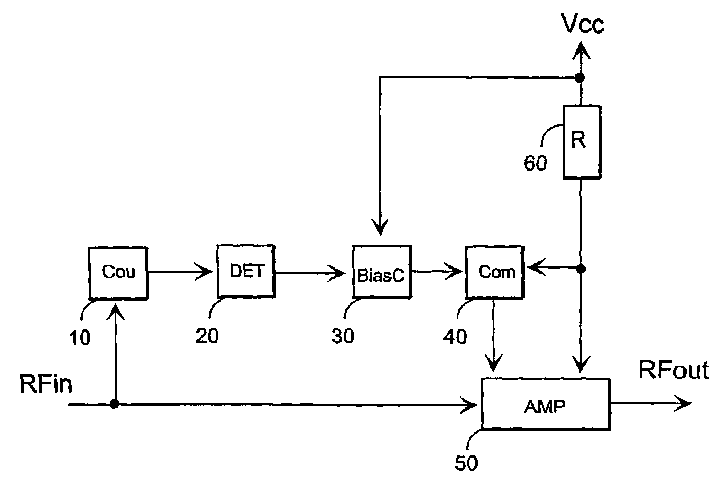
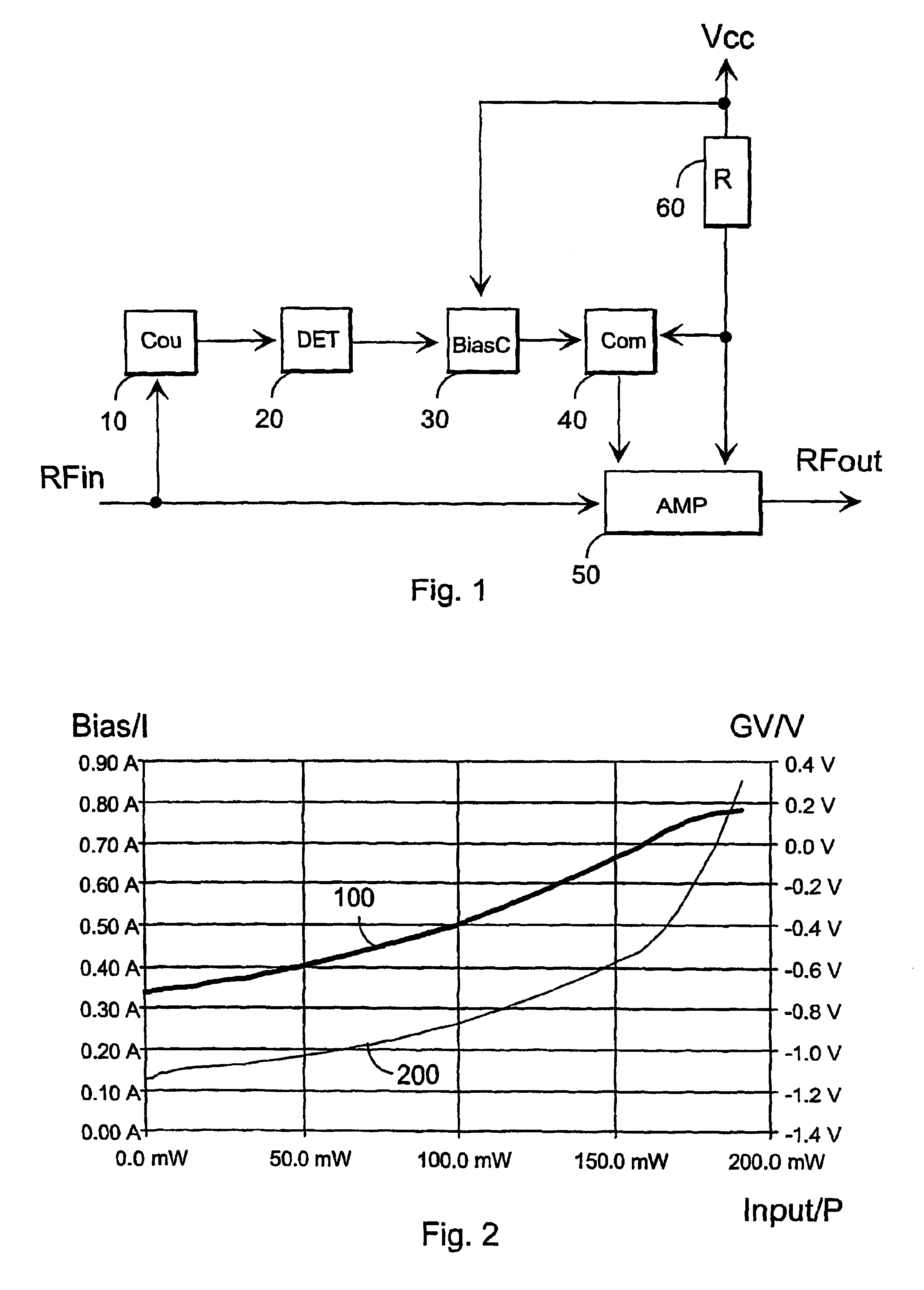
[0020]Referring to FIG. 1, an amplifier arrangement comprises a coupling device 10, a sampling device 20, a control device 30, an adjusting device 40, an amplifier 50 and a resistor 60. The amplifier arrangement is arranged to linearize an amplifier for a signal with a variable envelope.

[0021]The figure shows that an RF input signal is conveyed to the input of the amplifier 50, the RF input signal being amplified into an RF output signal in the amplifier. The signal applied to the input of the amplifier 50 has a variable envelope. The linearization method is suitable for use in amplifiers amplifying signals having power peaks much greater than an average power. Such signals occur e.g. in RF signals broadband-modulated using e.g. OFDMA or CDMA methods.

[0022]In the following, the invention is applied to the amplifier 50 meeting the criteria set for a so-called class A amplifier. Typically, a class A amplifier is extremely linear. The amplifier 50 shown in FIG. 1 can be implemented e.g...


PUM


Abstract

The invention relates to a linearization method and an amplifier arrangement for linearizing an amplifier (50) amplifying an RF signal with a variable envelope. The amplifier arrangement comprises a sampling device (20) for sampling an RF signal to be amplified. The amplifier arrangement further comprises a control device (30) arranged to generate, using samples, an output signal changing its value according to the envelope shape of the RF signal to be amplified. The amplifier arrangement further comprises an adjusting device (40) arranged to adjust, using the output signal, the bias current of the amplifier such that the magnitude of the output signal and the magnitude of the bias current change in the same direction.

Description

FIELD OF THE INVENTION[0001]The invention relates to a linearization method for an amplifier amplifying an RF signal with a variable envelope.BACKGROUND OF THE INVENTION[0002]Amplifier arrangements employ different linearization methods enabling the occurrence of interfering signals, such as distortions, noise and non-linear distortion, to be reduced in an output signal of an amplifier.[0003]U.S. Pat. No. 5,420,536, for example, discloses a non-linear amplifier linearization method based on a feedback circuit in an amplifier.[0004]In FI 9602814, linearization is carried out by predistorting a signal to be coupled to an output stage. The linearization is based on the fact that a device implementing the predistortion and the output stage have inverse operating characteristics compared with each other.[0005]The solution disclosed in U.S. Pat. No. 5,136,257 comprises measuring the output power of an amplifier, which is compared to a predicted value. The solution employs feedback, and in...

Claims


Application Information

Patent Timeline
Patent Type & Authority Patents(United States)
IPC IPC(8): H03F1/02H03F1/32
CPCH03F1/0266H03F1/32H03F2200/102H03F2200/451H03F2200/462H03F2200/99
Inventor IKONEN, RIKUALESTALO, LASSE
Owner ELEKTROBIT WIRELESS COMM OY
Why Eureka
Try Eureka