Condensate water recovering device

A technology for recycling device and condensate water, which is applied in the directions of supplementary water supply, preheating, steam generation, etc., which can solve the problems of high equipment failure rate, waste of waste heat of condensate water, and lower grade.

Inactive Publication Date: 2013-08-28
刘成红
View PDF0 Cites 5 Cited by
  • Summary
  • Abstract
  • Description
  • Claims
  • Application Information

AI Technical Summary

Problems solved by technology

[0002] The steam thermal system will generate a large amount of condensed water during operation. The temperature of the condensed water is above 100°C. However, in order to reduce the cost of equipment, the condensed water will be discharged at normal pressure before being recycled. The flash evaporati

Method used


Image

  • Condensate water recovering device

Examples


Embodiment Construction

[0010] In order to illustrate the present invention more clearly, an example is given for illustration, but the rights required by the present invention are not limited thereto:

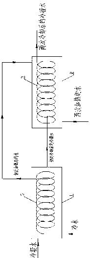
[0011] As shown in the figure, a condensed water recovery device is characterized by a condensed water heat exchanger (1), a condensed water heat exchanger (2), and a heat exchange tube (3).

[0012] The heat exchange tubes (3) in the condensed water heat exchanger (1) and the condensed water heat exchanger (2) are one or several types of composite tubes, coiled tubes or serpentine tubes.

[0013] The cold water entering the heat exchange tube (3) in the condensed water heat exchanger (1) is pushed in from the bottom.

[0014] Contains condensed water heat exchanger (1), condensed water heat exchanger (2), heat exchange tube (3), wherein the cold water enters the heat exchange tube (3) in the condensed water heat exchanger (1) and enters the condensed water The condensed water outside the heat excha...


PUM


Abstract

The invention provides a condensate water recovering device. Two condensate water heat exchangers are adopted by a heat pipe vacuum treatment method so that heat exchanging and cooling of condensate water in the normal-pressure closed state can be carried out, waste of waste heat of the condensate water can be reduced, and recovering cost of the condensate water can be lowered.

Description

technical field [0001] The invention relates to a condensed water recovery device, in particular to a condensed water recovery device suitable for condensed water containing impurities. Background technique [0002] The steam thermal system will generate a large amount of condensed water during operation, and the temperature of the condensed water is above 100°C. However, in order to reduce the cost of equipment, the condensed water will be discharged at normal pressure before being recycled. The flash evaporation will cause a large amount of condensed water waste heat. Wasteful and less tasteful. In addition, when there are many impurities in the condensed water, recycling with mechanical devices such as reciprocating pumps will cause problems such as high failure rate and short service life of the equipment. Contents of the invention [0003] The purpose of the present invention is to propose a technical solution for a condensed water recovery device that enables the co...

Claims


Application Information

Patent Timeline
IPC IPC(8): F22D11/00F28D7/00
Inventor 刘成红
Owner 刘成红
Why Eureka
Try Eureka