
Structure for fastening sword blade to scabbard

a technology for fastening structures and sword blades, which is applied in the direction of thrusting weapons, white arms/cold weapons, weapons, etc., can solve the problems of blades that cannot be smoothly drawn out of the scabbard, and cannot be securely received, so as to achieve safe and secure insertion into the scabbard, easy to be safely received and retained, and easy to be drawn ou

Inactive Publication Date: 2008-01-24
CHANG KUO CHI
View PDF9 Cites 11 Cited by
  • Summary
  • Abstract
  • Description
  • Claims
  • Application Information

AI Technical Summary

Benefits of technology

[0004]A primary object of the present invention is to provide a structure for fastening a sword blade to a scabbard, so that the sword blade is safely received in and retained to the scabbard without the risk of unexpectedly moving out of the scabbard, and can be smoothly drawn out from the scabbard as desired.
[0005]To achieve the above and other objects, the fastening structure of the present invention includes two magnets having different polarities and imbedded in the sword blade and the scabbard, respectively. The magnet imbedded in the sword blade is flush with an outer surface of the sword blade near a cross guard of a sword, and the magnet imbedded in the scabbard is flush with an inner surface of the scabbard corresponding to the magnet on the sword blade. With this arrangement, the sword blade may be easily inserted into the scabbard without the need of particularly aligning the blade with the scabbard, and may be drawn out of the scabbard smoothly without the risk of being stuck to the scabbard.

Problems solved by technology

While the sword blade is produced to highly match with the scabbard to avoid unexpected separation of the sword from the scabbard, it is also possible the sword blade is stuck to the scabbard and could not be smoothly drawn out from the scabbard.
Moreover, the blade might become too tightly or loosely fitted in the scabbard due to errors in size and / or thermal expansion, and fails to be smoothly drawn out of the scabbard or securely received in the scabbard, respectively.

Method used


Image

  • Structure for fastening sword blade to scabbard
  • Structure for fastening sword blade to scabbard
  • Structure for fastening sword blade to scabbard

Examples


Embodiment Construction

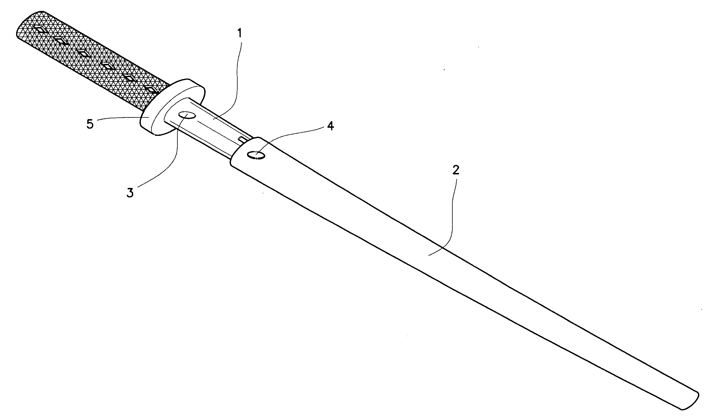
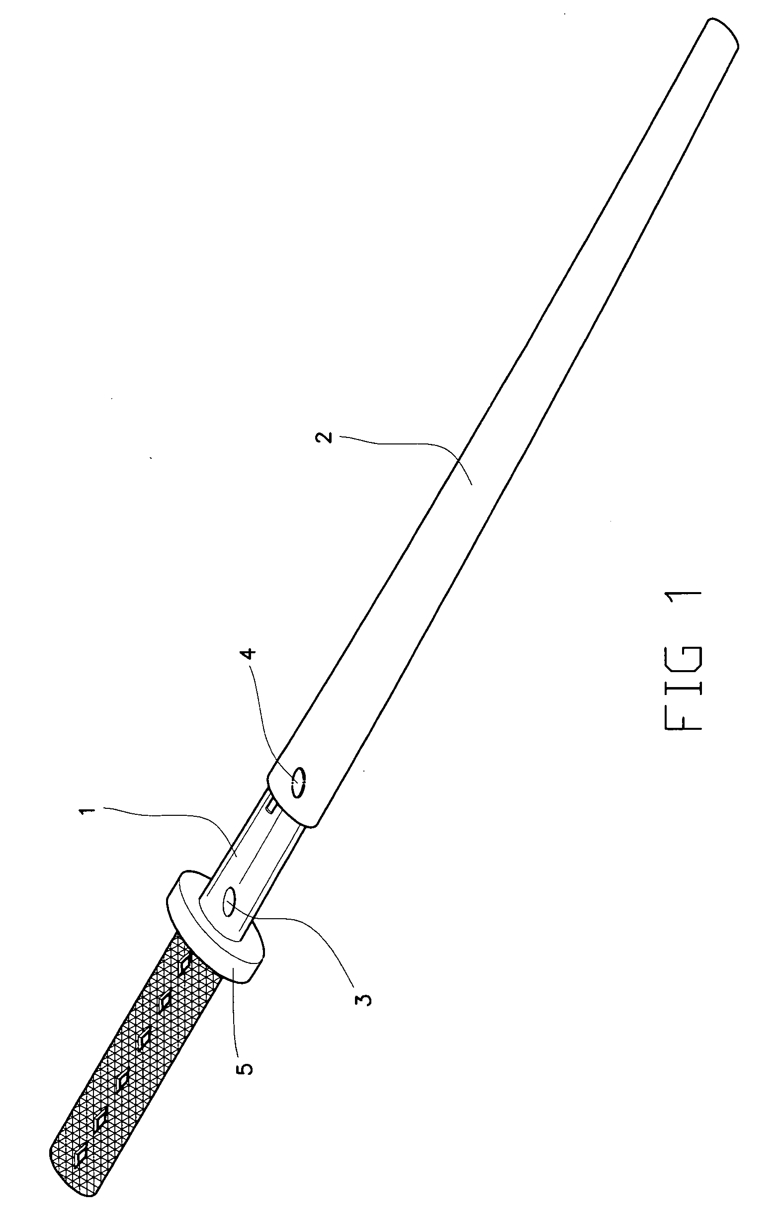
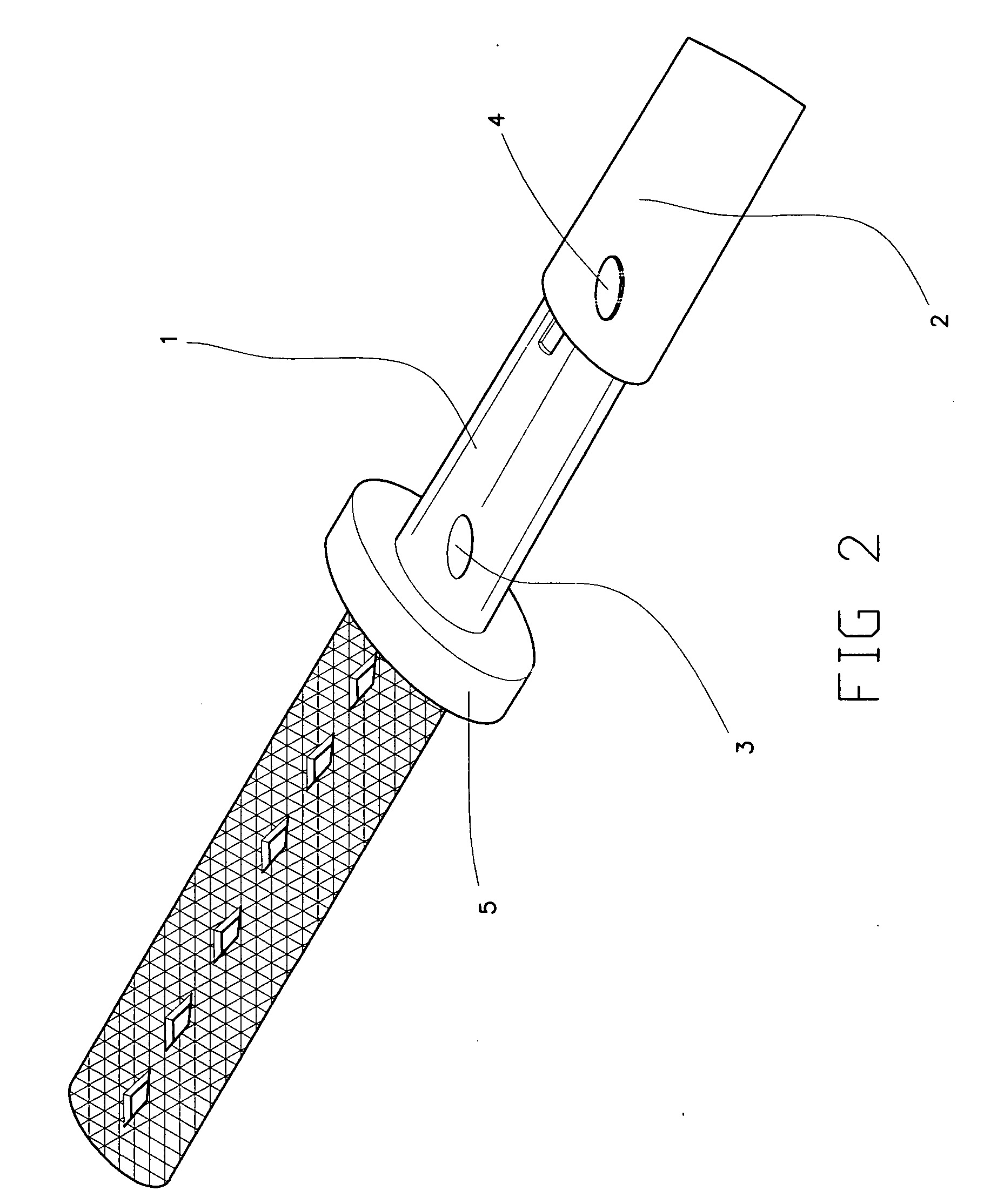
[0010]Please refer to FIGS. 1 and 2. The present invention relates to a structure for fastening a blade 1 to a scabbard 2 of a sword. The fastening structure is imbedded in the blade 1 and the scabbard 2. With the fastening structure of the present invention, the sword blade 1 received in the scabbard 2 is securely held to the scabbard 2, and may be smoothly drawn out of the scabbard 2 without the risk of being stuck to the scabbard 2.

[0011]The structure for fastening the sword blade 1 to the scabbard 2 according to the present invention includes a set of two magnets 3, 4 imbedded in the sword blade 1 and the scabbard 2, respectively. The two magnets have different polarities. That is, the magnet 3 has a positive polarity when the magnet 4 has a negative polarity, and vice versa. The magnet 3 is flush with an outer surface of the sword blade 1 near a cross guard 5 of the sword, and the magnet 4 is flush with an inner surface of the scabbard 2 near an opening thereof and correspondin...


PUM


Abstract

A structure for fastening sword blade to scabbard includes two magnets having different polarities and imbedded in a blade and a scabbard of a sword, respectively. The magnet imbedded in the blade is flush with an outer surface of the blade near a cross guard of the sword, and the magnet imbedded in the scabbard is flush with an inner surface of the scabbard corresponding to the magnet on the blade. With these arrangements, the sword blade may be easily inserted into and magnetically held to the scabbard without the risk of unexpectedly moving out of the scabbard, and may be smoothly drawn out from the scabbard without the risk of being stuck to the scabbard.

Description

FIELD OF THE INVENTION[0001]The present invention relates to a structure for fastening sword blade to scabbard, and more particularly to a fastening structure including two magnets having different polarities for correspondingly imbedding in a sword blade and a scabbard, so as to magnetically hold the blade in the scabbard while allowing the blade to be smoothly drawn from the scabbard without being stuck thereto.BACKGROUND OF THE INVENTION[0002]To prevent a blade from unexpectedly moving out of a scabbard of a sword, a sword manufacturer would usually try to produce the scabbard as highly matching with the sword blade as possible. While the sword blade is produced to highly match with the scabbard to avoid unexpected separation of the sword from the scabbard, it is also possible the sword blade is stuck to the scabbard and could not be smoothly drawn out from the scabbard. Moreover, the blade might become too tightly or loosely fitted in the scabbard due to errors in size and / or th...

Claims


Application Information

Patent Timeline
IPC IPC(8): B26B3/06
CPCF41B13/04
Inventor CHANG, KUO CHI
Owner CHANG KUO CHI
Learn More