Test body clamping device in a rheometer

a clamping device and rheometer technology, applied in the direction of measuring devices, scientific instruments, instruments, etc., can solve the problems of large tensile force formation in the clamping device, falsification of measurement, time-consuming and difficult procedures,

Inactive Publication Date: 2006-11-23
THERMO ELECTRON KARLSRUHE
View PDF8 Cites 3 Cited by
  • Summary
  • Abstract
  • Description
  • Claims
  • Application Information

AI Technical Summary

Benefits of technology

[0019] The adjustment screw preferably comprises an inner axial recess or bore by means of which it is seated on a bearing pin of the drive part, such that it can be freely displaced. The clamping spring may thereby be disposed inside the recess and be supported on the bearing pin and also on the bottom of the recess. This has the further advantage that the clamping spring is la...

Problems solved by technology

This procedure is time-consuming and difficult and moreover requires storage of a plurality of different contact blocks.
This eccentricity generates moments which can falsify the measuring results.
At very high temperatures, very...

Method used


Image

  • Test body clamping device in a rheometer
  • Test body clamping device in a rheometer
  • Test body clamping device in a rheometer

Examples


Embodiment Construction

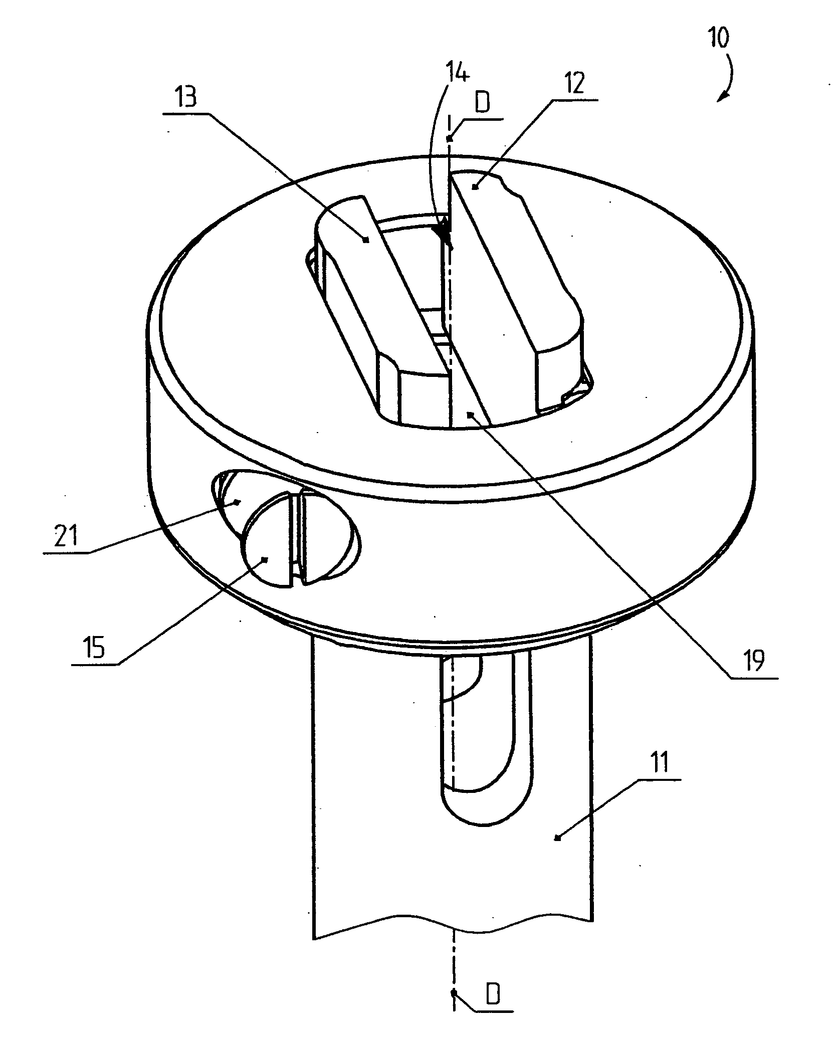
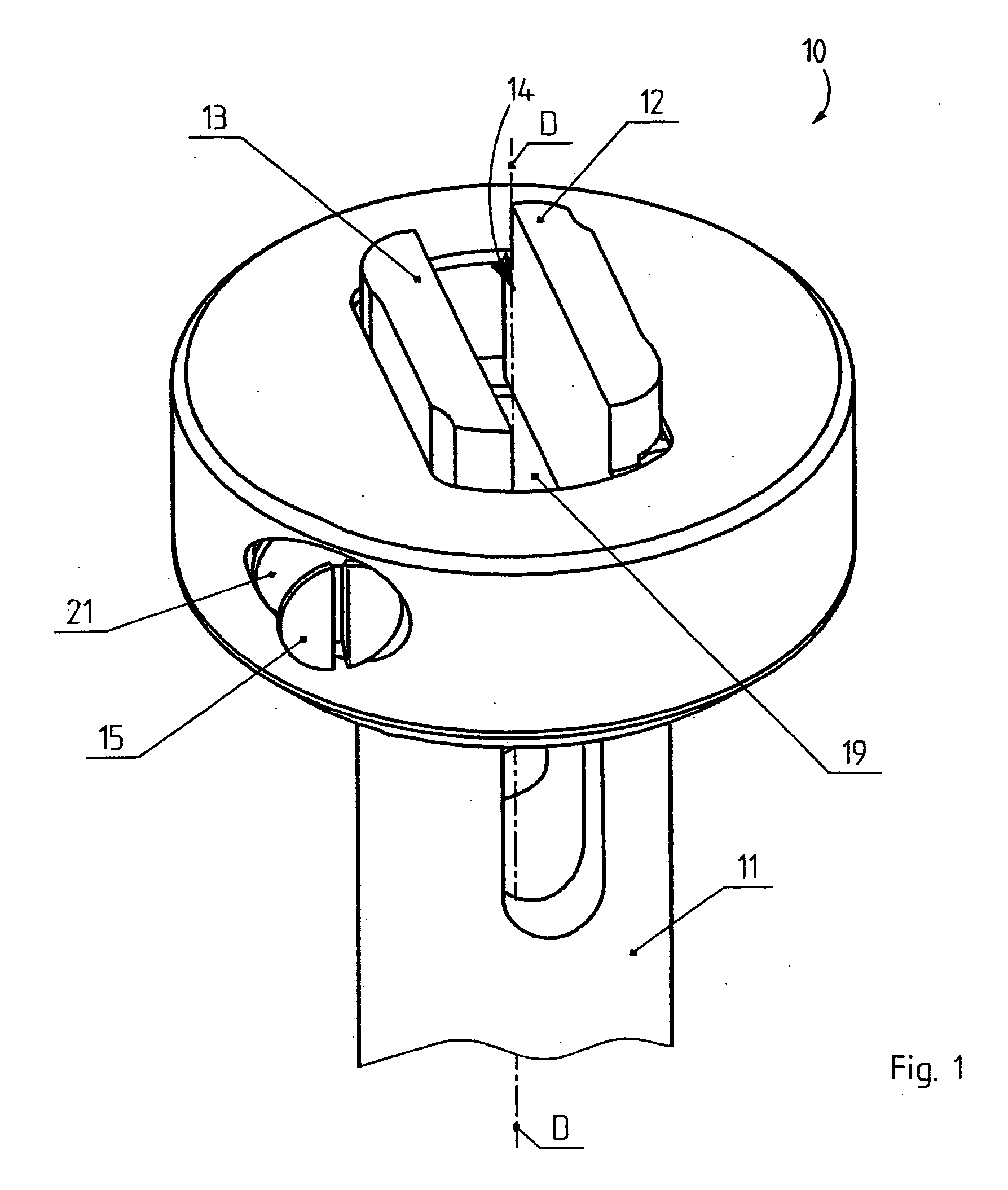
[0032]FIG. 1 shows a test body clamping device 10 which is disposed on a shaft 11 of a rotational rheometer. The shaft 11 can be rotated together with the test body clamping device 10 about a longitudinal axis D.

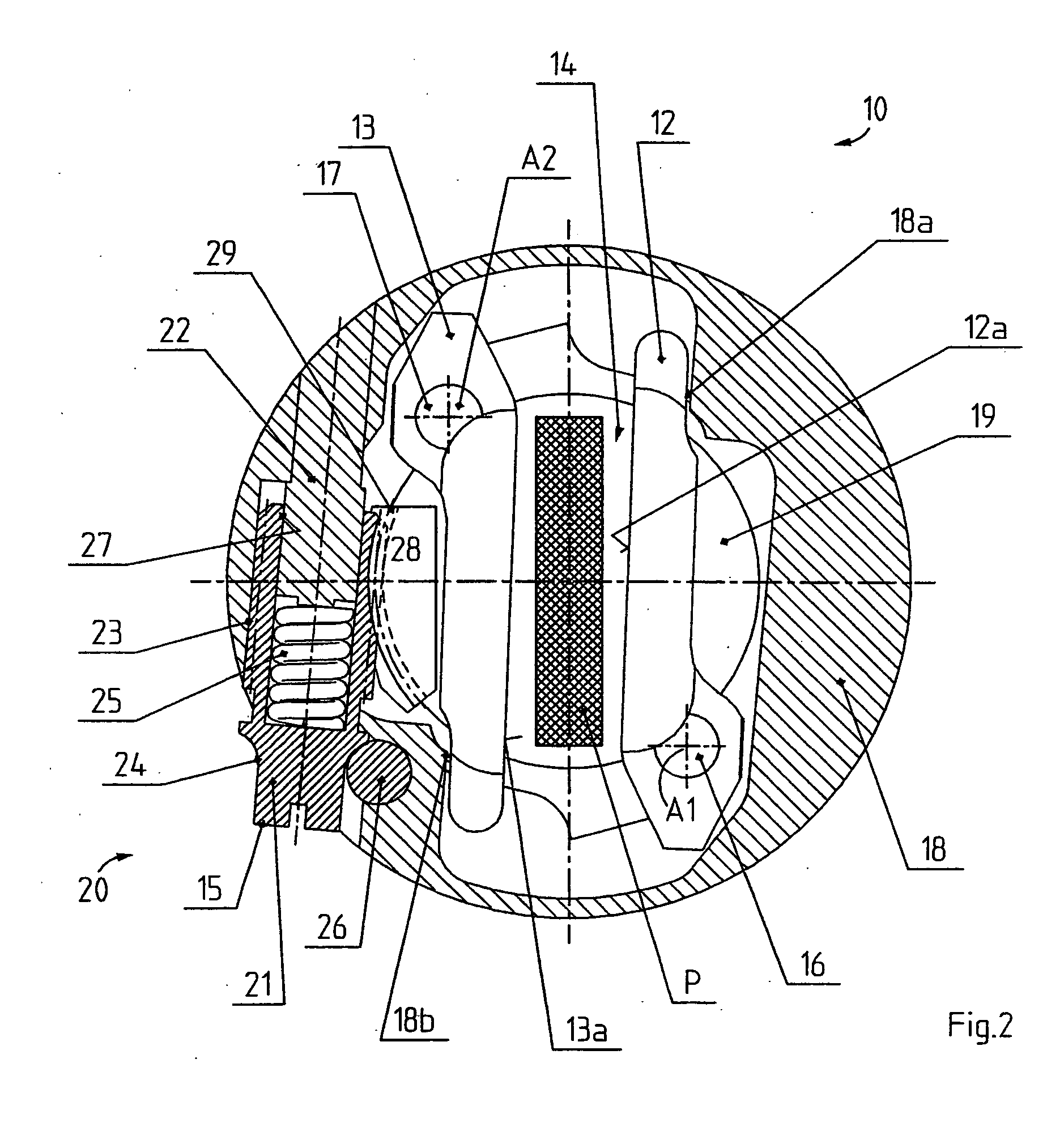
[0033] The test body clamping device 10 comprises two clamping jaws 12, 13 between which a receiving space 14 is formed for receiving a test body P (FIG. 2). FIG. 1 shows an adjustment screw 21 having an operating section 15, the rotation of which moves the two clamping jaws 12, 13 towards each other or away from each other, thereby clamping or releasing the test body P.

[0034] In FIG. 2, a bottom part 19 is rigidly mounted to the shaft 11 and bears one bearing pin 16 and 17 at each of two locations disposed diametrally opposite relative to the longitudinal axis D. One clamping jaw 12, 13 is rotatably disposed on each bearing pin 16 and 17, such that the clamping jaw 12 on the right in FIG. 2 can be pivoted about an axis of rotation A1 and the clamping jaw 13 on the left in...


PUM


Abstract

A test body clamping device in a rheometer comprises two clamping jaws between which a test body can be clamped, and an operating device for moving the clamping jaws towards and away from each other. The invention provides that each clamping jaw is pivotably disposed about an axis, wherein the axes extend parallel to each other and parallel to a clamping surface of the respective clamping jaw. The clamping jaws moreover have an associated common drive part for exerting a drive force onto both clamping jaws, which produces a synchronized pivoting motion of both clamping jaws, wherein the clamping jaws are subjected, in their clamped position, to the action of a common clamping force element, in particular a clamping spring.

Description

[0001] This application claims Paris Convention priority of DE 10 2005 021 121.6 filed May 6, 2005 the complete disclosure of which is hereby incorporated by reference. BACKGROUND OF THE INVENTION [0002] The invention concerns a test body clamping device in a rheometer, comprising two clamping jaws, between which a test body can be clamped, and an operating device for moving the clamping jaws towards each other. [0003] A rheometer, in particular, a rotational rheometer is conventionally used to determine the rheological values or characteristic values of a viscous substance. The rheometer comprises a lower measuring part and an upper measuring part which can be adjusted relative to each other. The upper measuring part of a rotational rheometer can be rotated and oscillated. A sample space is formed between the measuring parts for receiving a sample of the substance to be investigated. The forces and torques generated through relative adjustment between the upper and lower measuring ...

Claims


Application Information

Patent Timeline
IPC IPC(8): G01N3/02
CPCG01N2203/0226G01N3/04
Inventor PLATZEK, WOLFGANG
Owner THERMO ELECTRON KARLSRUHE
Why Eureka
Try Eureka