Multi-Chamber, Explosion-Proof, Battery-Testing Apparatus

a battery test and multi-chamber technology, applied in the field of battery testing, can solve the problems of destroying adjacent batteries and equipment within the box, affecting the safety of workers, so as to improve the heat exchange efficiency, increase the surface area, and increase the heat conduction area

Active Publication Date: 2020-02-27
ZHANG CHAOJIONG
View PDF0 Cites 13 Cited by
  • Summary
  • Abstract
  • Description
  • Claims
  • Application Information

AI Technical Summary

Benefits of technology

[0018]The surface on the side of the cooling plate facing the explosion-proof door is preferably an inclined surface, and a heat dissipation grille is preferably disposed on the inclined surface. The lower end of the metal cooling plate is preferably fixed to the circuit board, and the arrangement of the inclined surface increases the heat conduction area, which is more favorable for heat conduction to the horizontal plate of the cooling plate, thereby further improving the heat exchange efficiency.
[0019]The cooling plate further includes a horizontal plate extending toward and close to the door. Through this structure, a very effective heat conduction surface can be provided to the battery under test, and the tested battery can be directly in contact with the heat conduction surface to exchange heat directly, which is more efficient than indirect heat exchanged through air as a heat conduction medium through the temperature control box. The heat conduction surface is not limited to flat surfaces. The cooling plate can also be shaped to form a cavity for the tested battery, which increases the surface area through which a b...

Problems solved by technology

During the tests, the batteries may explode, burn, and even endanger the safety of the workers.
If an abnormality such as an explosion or burning occurs in the testing of the charge and discharge of any individual battery, it will damage adjacent batteries and equipment within the box.
In addition, existing test boxes can only regulate the internal temperature of the one single cabinet, and cannot meet the specific environmental tem...

Method used


Image

  • Multi-Chamber, Explosion-Proof, Battery-Testing Apparatus
  • Multi-Chamber, Explosion-Proof, Battery-Testing Apparatus
  • Multi-Chamber, Explosion-Proof, Battery-Testing Apparatus

Examples


Embodiment Construction

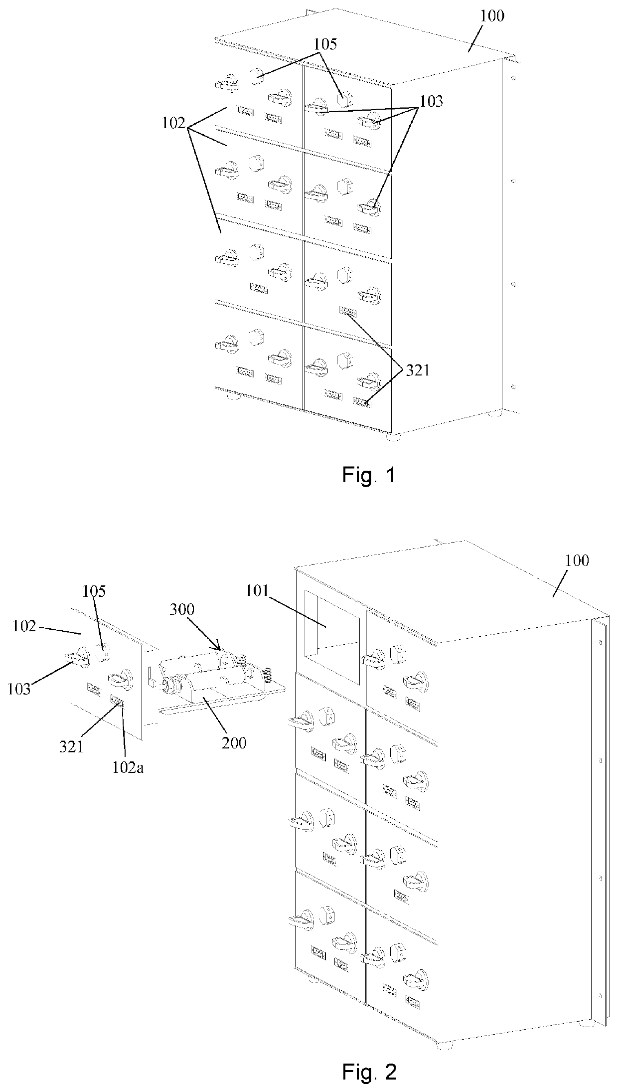
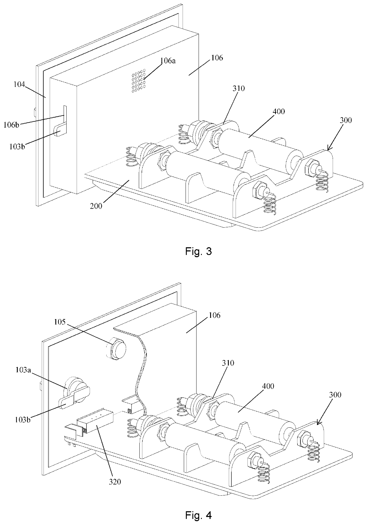
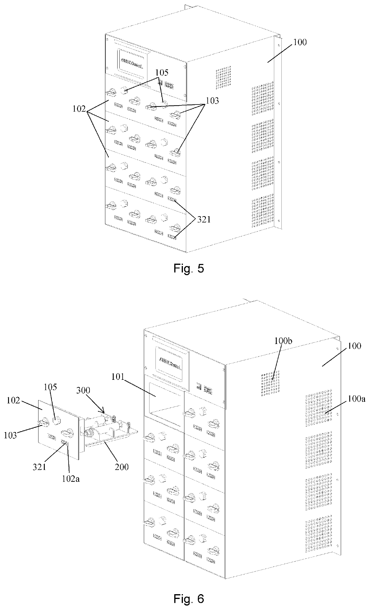
[0033]The invention and specific embodiments thereof will be further described in detail below with reference to the drawings. With reference to FIGS. 1-4, one embodiment of the present invention provides a multi-chamber, independent, explosion-proof, fireproof, isolation box, which includes a box 100. Box 100 has opposing front and back sides, opposing top and bottom sides, opposing left and right sides and inside dividing walls. The inside dividing walls and the sides of the box define a plurality of chambers. The front side of the box is generally open with an open framework around the chambers. A plurality of independent, explosion-proof chambers 101 are arranged in the box 100. An explosion-proof door 102 encloses each chamber 101. The explosion-proof door 102 is provided with two left and right rotary locks 103. With reference to FIG. 4, rotary lock 103 includes a main body portion 103a and a rotating locking lever 103b. The main body portion 103a is mounted on the explosion-p...


PUM


Abstract

A cabinet box comprises a plurality of independent, explosion-proof chambers. A battery wiring assembly for receiving and testing a battery is attached to an inner wall of an explosion-proof door, and an electrical connector is provided on an outer wall of the door. The assembly is placed inside a chamber, and the door seals the chamber. The temperature in each chamber is controlled independently, allowing batteries to be tested simultaneously at different temperatures. An air-circulating temperature-control module can be in a chamber, or a temperature controller with a refrigeration sheet can be integrated with the battery wiring assembly for direct battery contact. Separate, independent explosion-proof chambers effectively eliminate the possibility of a battery explosion in one chamber causing a chain-reaction explosion in another chamber. Modularity allows damaged parts to be replaced easily. An external battery testing machine can connected to the connector on each door.

Description

CROSS-REFERENCE TO RELATED APPLICATIONS[0001]This application claims priority to Chinese Invention Patent Application No. 201810978190.2 and to Chinese Utility Model Application No. 201821380223.5, both of which were filed on Aug. 27, 2018, and each of which is incorporated by reference. This application also claims priority to U.S. Provisional Patent Application No. 62 / 817,326 filed on Mar. 12, 2019, which is incorporated by reference.BACKGROUND OF THE INVENTION1. Field of the Invention[0002]This patent application pertains to battery testing, and more particularly to a multi-chamber, independent, explosion-proof, fireproof, isolation box in which batteries are placed for testing so that a battery explosion is contained within one chamber without disrupting testing in other chambers within the box. The temperature in each chamber is controlled independently of other chambers within the box.2. Description of the Related Art[0003]Batteries are being used more and more frequently in p...

Claims


Application Information

Patent Timeline
IPC IPC(8): G01R31/36G01R31/385G01R31/371G12B17/08
CPCG01R31/371G01R31/385G12B17/08G01R31/3644G01R31/3865G01R1/44G01R1/04
Inventor ZHANG, CHAOJIONG
Owner ZHANG CHAOJIONG
Why Eureka
Try Eureka