
Vehicle interior member and method for removal thereof

a technology for interior members and vehicles, applied in vehicle arrangements, roofs, monocoque constructions, etc., can solve problems such as degrading work efficiency, clip loss, pressure plug dropping or losing when being attached or removed,

Inactive Publication Date: 2008-01-24
DAIKYONISHIKAWA CORP
View PDF13 Cites 45 Cited by
  • Summary
  • Abstract
  • Description
  • Claims
  • Application Information

AI Technical Summary

Benefits of technology

[0006]Therefore the present invention has the object of providing an affixing member, a vehicle interior member furnished therewith, and a method for removal thereof, capable of improving the work efficiency of attachment and removal.

Problems solved by technology

However, the attaching structure set forth in JP2003-226182 has the problem that when a clip is elastically deformed in order to remove an assist grip, the dip can be mistakenly caused to fall down inside an opening in a body panel or a bracket affixed to a body panel.
If a clip is dropped into the inside of a body panel opening it is difficult in typical vehicle structures to recover the clip, and even if dropped from an opening in a bracket, the clip can be lost, in both cases greatly degrading work efficiency.
Furthermore, in the attaching structure set forth in Japanese Patent 2003-226182, the assist grip can be more reliably affixed by a pressure plug, but there is a danger that the pressure plug will be dropped or lost when being attached or removed.

Method used


Image

  • Vehicle interior member and method for removal thereof
  • Vehicle interior member and method for removal thereof
  • Vehicle interior member and method for removal thereof

Examples


Embodiment Construction

[0028]Next, referring to the attached diagrams, we shall explain a vehicle interior member according to a preferred embodiment of the present invention. We here explain the case in which the present invention is applied to an assist grip, which is one type of vehicle interior member.

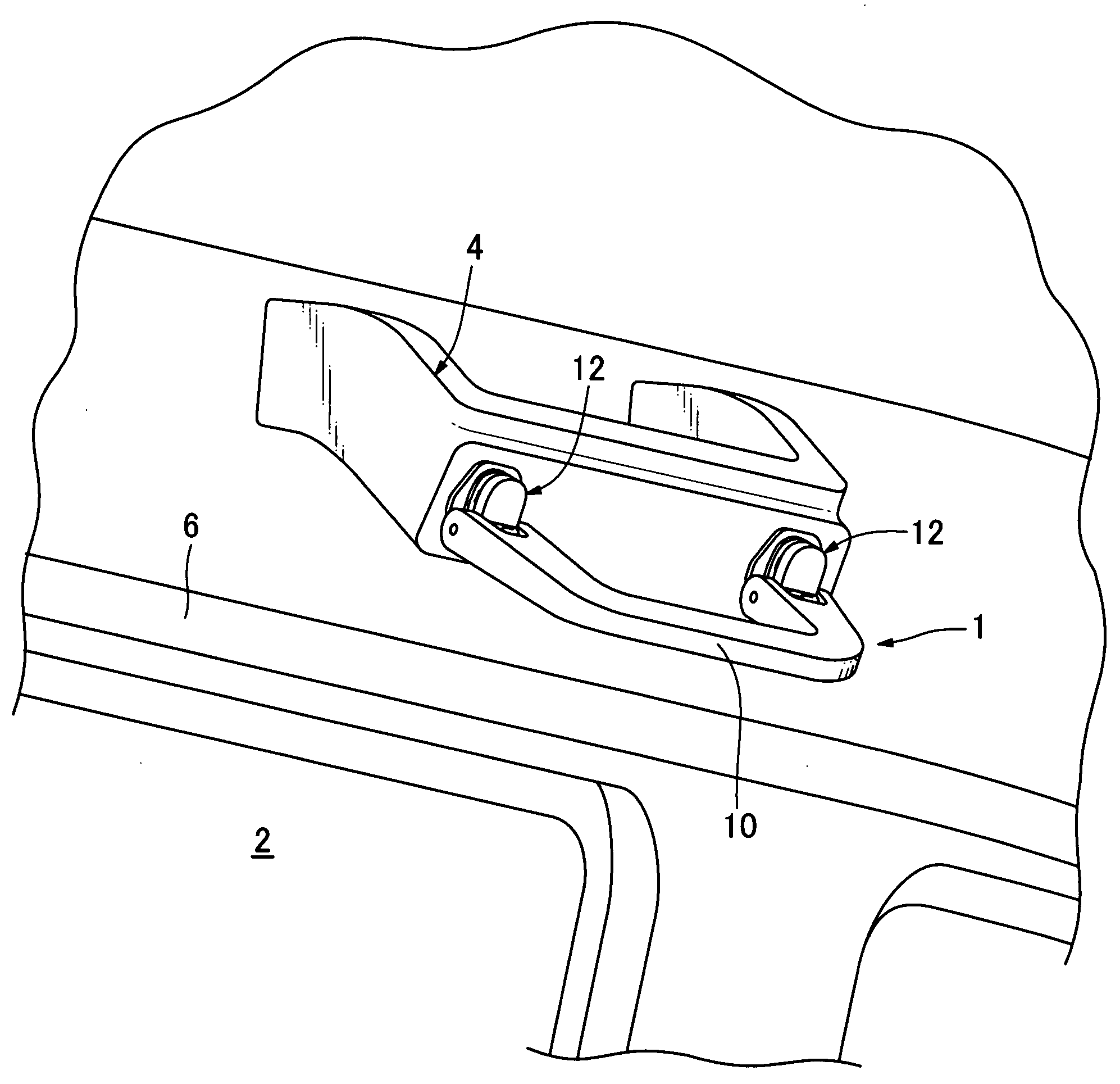
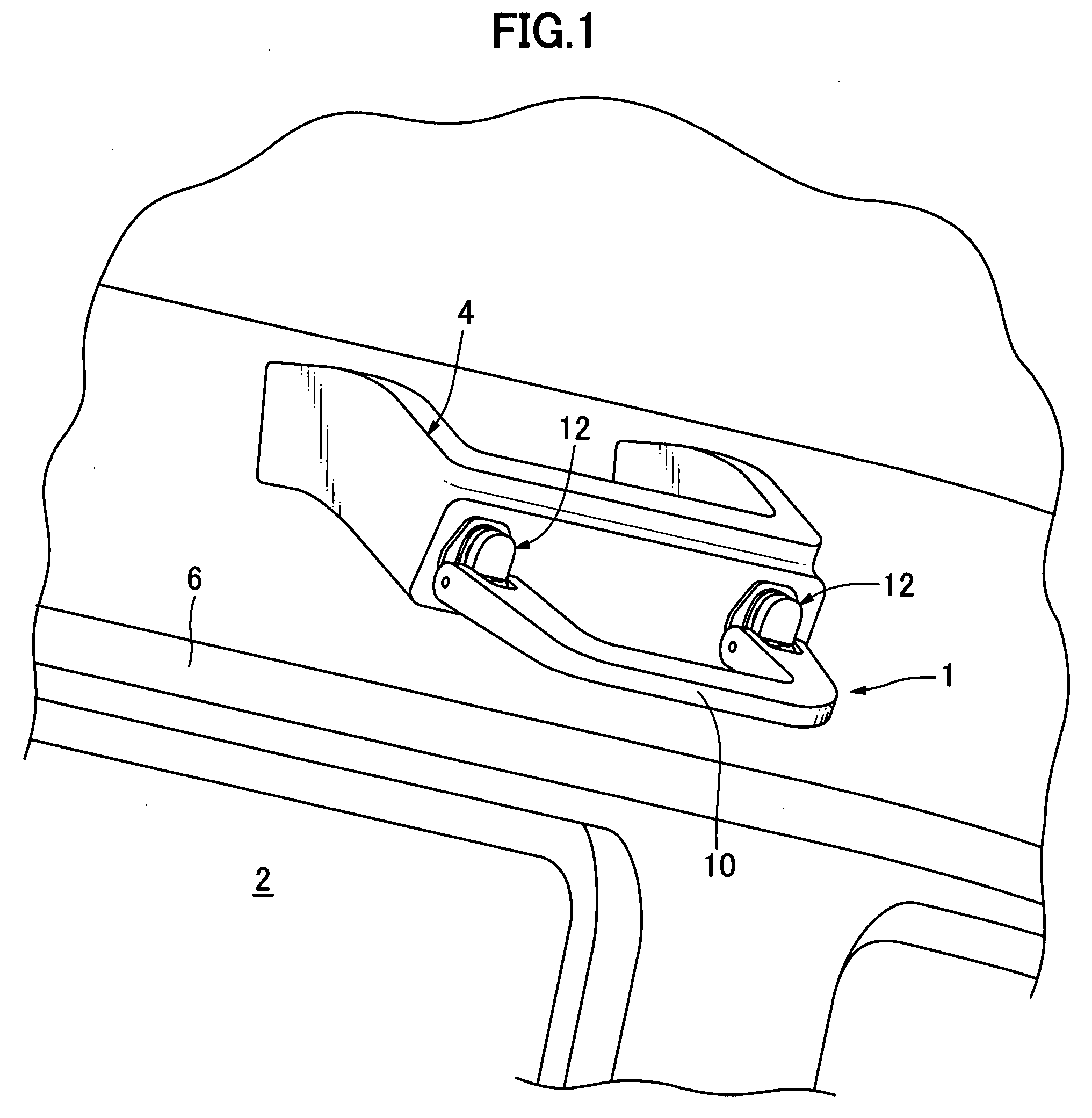
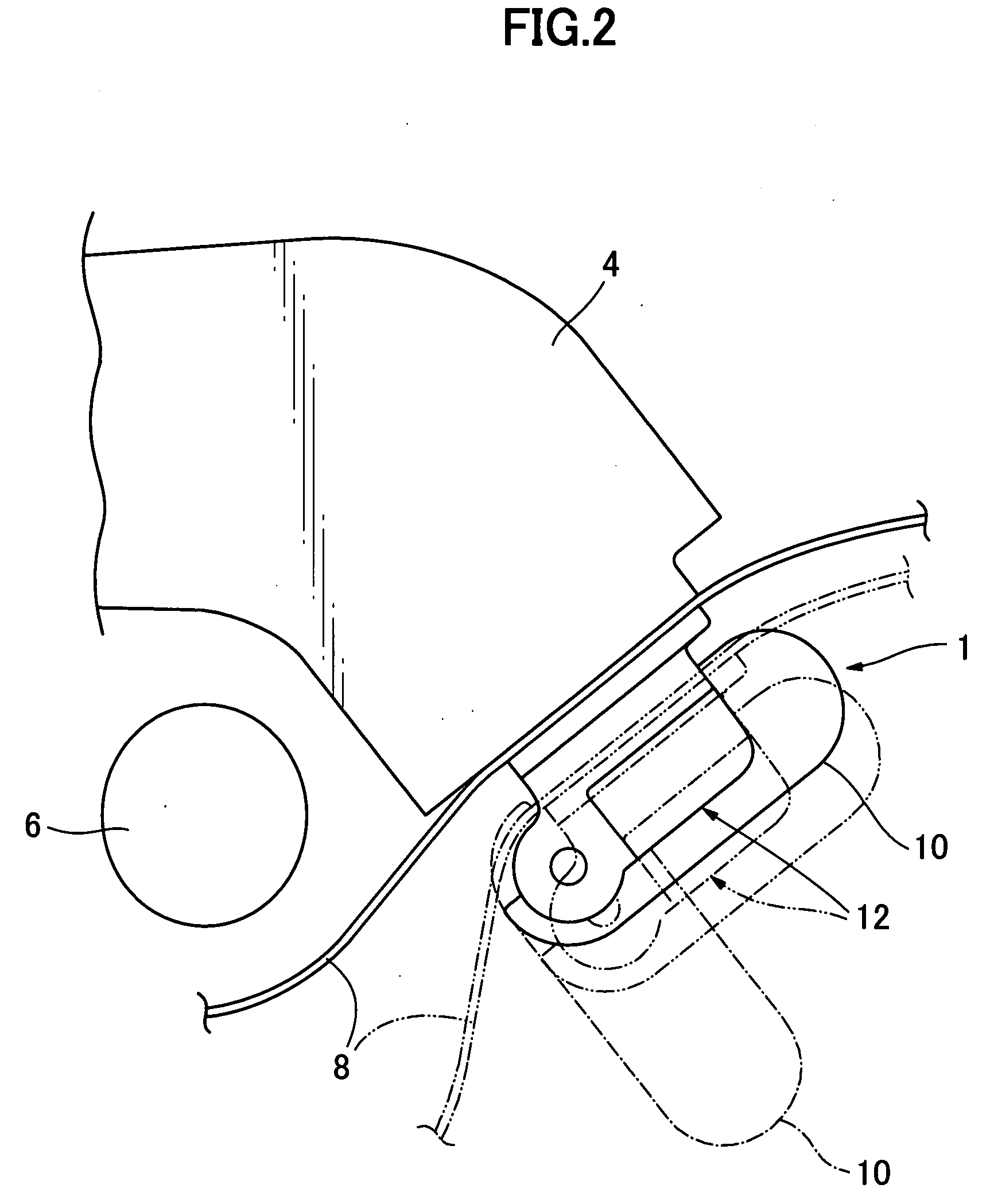
[0029]FIG. 1 is a perspective view showing the appearance of an assist grip according to an embodiment of the present invention attached to the upper portion of a side surface inside a vehicle cabin. FIG. 2 is a side view of the appearance as seen from the front of a vehicle showing an assist grip according to an embodiment of the present invention, attached to a bracket.

[0030]As shown in FIGS. 1 and 2, an assist grip 1 according the present embodiment is attached above a window 2 on the vehicle side wall to the vehicle body through a bracket 4, which is an attaching portion. A curtain airbag 6 is disposed dose to and under the bracket 4. Moreover, roof trim 8 (FIG. 2) is attached so as to cover the brac...


PUM


Abstract

Problem: To provide a vehicle interior member affixing member capable of improving the efficiency of attachment and removal operations.Means for Solving the Problem: The present invention is a vehicle interior member (1) attached to an attaching portion (4) in a vehicle cabin having an interior member main body (14) and an affixing member (16) for attaching the interior member main body, wherein the affixing member comprises two inserted portions (16a, 16b) inserted at the leading end side into an opening portion and mutually separated, a tab portion (16d) disposed on these inserted portions and engaging the edge portions of the opening portion when attached, thereby preventing the affixing member from falling out, and a connecting portion (16c) connecting the two inserted portions in such a way that the width at the base end side is approximately the same as the width at the opening portion; when the interior member main body is attached, the two inserted portions are placed at a spacing such that the tab portions engage the opening portions, and when pulled out, they are elastically deformed such that the gap at the leading end side of the inserted portions narrows and the engagement between the tab portion and the opening portion is released.

Description

TECHNICAL FIELD OF THE PRESENT INVENTION[0001]The present invention relates to an affixing member, a vehicle interior member equipped therewith, and a method for removal thereof, and in particular relates to an affixing member for attaching an interior portion main body to an attaching portion disposed within a vehicle cabin, a vehicle interior member furnished therewith, and a method for removal thereof.BACKGROUND ART[0002]An attaching structure and attaching method for an automobile interior part is set forth in Japanese Patent Laid-Open No. 2003-226182 (Patent Document 1). This document sets forth an attaching structure for an automobile interior part such as an assist grip or the like attached inside a vehicle cabin. In this attaching structure, the assist grip is attached to an automobile body panel using a clip formed from a thin metal sheet. This metal clip is formed by bending a long and narrow metal sheet such that it becomes tapered at one end; the bent dip end side is ins...

Claims


Application Information

Patent Timeline
Patent Type & Authority Applications(United States)
IPC IPC(8): B60N3/02
CPCB60N3/026
Inventor YAMAGIWA, TSUYOSHIHIDAKA, SHOUICHIROUKIKKAWA, HIDEAKI
Owner DAIKYONISHIKAWA CORP
Features
  • Generate Ideas
  • Intellectual Property
  • Life Sciences
  • Materials
  • Tech Scout
  • Unparalleled Data Quality
  • Higher Quality Content
  • 60% Fewer Hallucinations
Learn More