Digital holographic microscope for 3D imaging and process using it

a holographic microscope and 3d imaging technology, applied in the field of digital holographic microscopes, can solve the problems of insufficient quality of obtained images, inability to use partially coherent illumination sources, and insufficient microscopy applications, etc., to reduce spatial coherence, reduce coherent noise, and reduce fringe contrast

Inactive Publication Date: 2008-01-24
UNIV LIBRE DE BRUXELIES
View PDF2 Cites 77 Cited by
  • Summary
  • Abstract
  • Description
  • Claims
  • Application Information

AI Technical Summary

Benefits of technology

[0086]The “spatial partial coherence” quantifies the statistical phase correlation of a light distribution in a plane at any couple of points. It can be shown that reducing the spatial coherence in an optical imaging system reduces the coherent noise originated from the light scattering, the multiple reflections and the defects of the optical set up 15-18, 24.
[0087]The “temporal coherence” is related to the spectral width of an optical source and establishes the reduction of fringe contrast when there is an optical path difference between the beams of a two optical paths interferometer. The reduction of the temporal coherence results also in a reduction of the coherent noise in an imaging system 29.

Problems solved by technology

It results that shearography interferometers in general, and in particular the shearography interferometer disclosed in the document U.S. Pat. No. 5,257,089, is not conceived so as to allow an accurate adjustment of the interferometric paths, which makes them unusable with illumination sources such as partially coherent illumination sources.
However the quality of the obtained images is not sufficient for microscopy applications, on the contrary to digital holography.
However, this apparatus uses a laser beam, as very often in holography, which is a source of coherent noise in the obtained results.
However, this apparatus has the same drawback as the previous one as it also uses a laser source.
However, this configuration is limited to specific applications requiring reflection illumination mode.
This apparatus provides very high quality results but hence requests for each new sample complex optical adjustments.
Although this microscope is powerful, it requires to differentiate the fluorescent parts of the sample from the background for the digital holographic signal, and it cannot work with only fluorescent illumination.
However, the filtering process in the reference beam considerably changes the illumination level and the coherence properties of the reference beam.
In addition, the digital holographic reconstruction is less powerful, leading to a significant decrease of the resolution.
Moreover, as attested by the publications, the image quality is rather poor.
In other words, the apparatus according to the prior art present technical constraints such as the choice of a limited range of illumination sources, multiple and complex adjustments, complexity of data treatments, reliability of the three-dimensional reconstruction, limited image quality.

Method used


Image

  • Digital holographic microscope for 3D imaging and process using it
  • Digital holographic microscope for 3D imaging and process using it
  • Digital holographic microscope for 3D imaging and process using it

Examples


first preferred embodiment

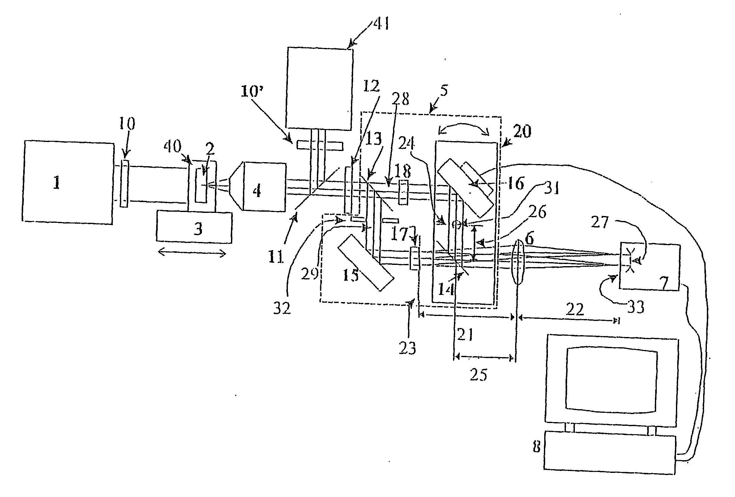
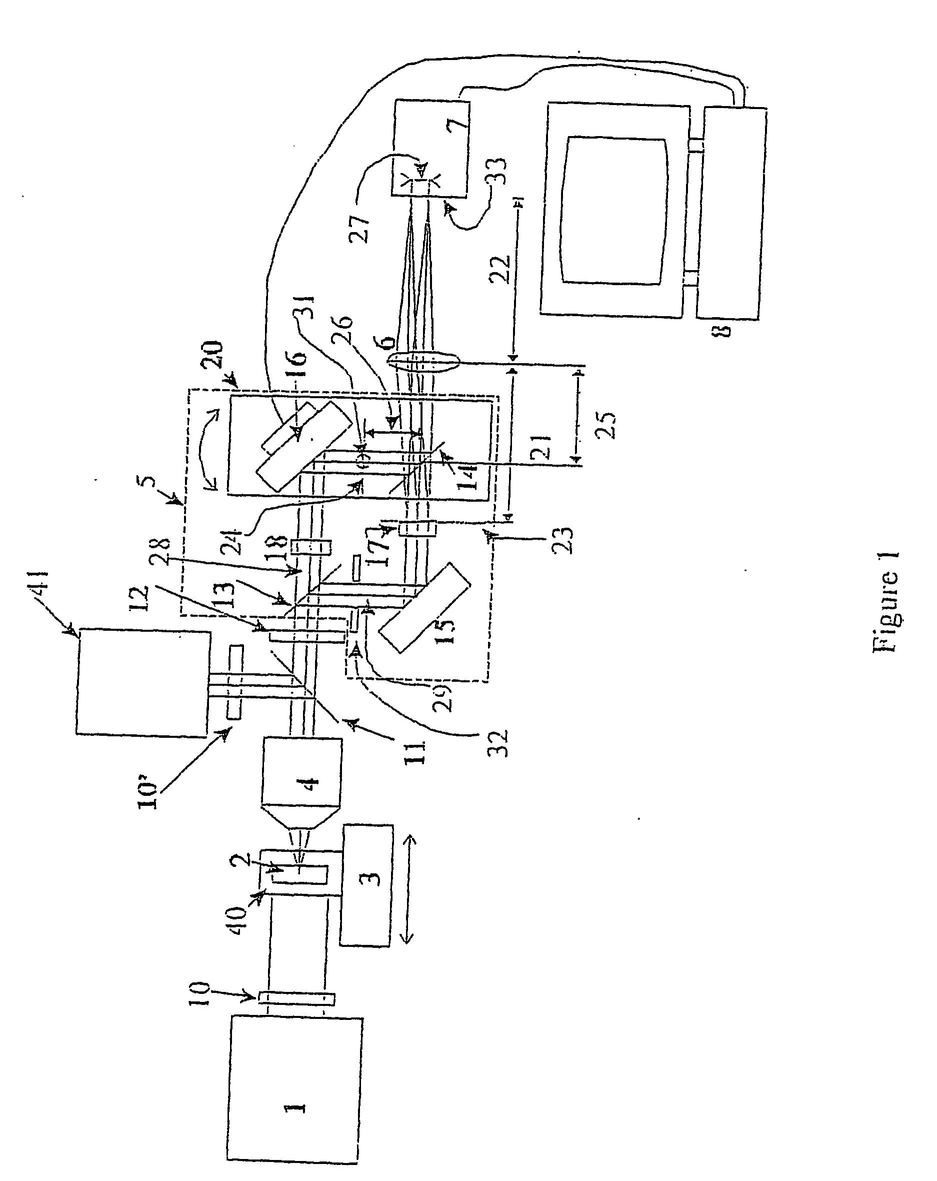
[0095]A first preferred embodiment of the microscope according to the present invention is present in FIG. 1.

[0096]As shown by FIG. 1, in said first preferred embodiment, the microscope comprises illumination means 1 able to work in a transmission mode and illuminations means 41 able to work in a reflection mode. In this preferred embodiment, the microscope is thus able to work selectively in transmission mode or in reflection mode by selectively switching on the adequate illumination means 1 or 41, respectively, while the other illumination means 41 or 1 respectively remains switched off.

[0097]However, it is obvious for the man skilled in the art that a microscope according to the invention may comprise only one of said illumination means 1 or 41.

[0098]Said illumination means 1, 41 are partially coherent, and have to present, at least, partial temporal coherence. 41.

[0099]The microscope as illustrated in FIG. 1 also comprises a sample holder 40 able to receive a sample 2 under inve...

second preferred embodiment

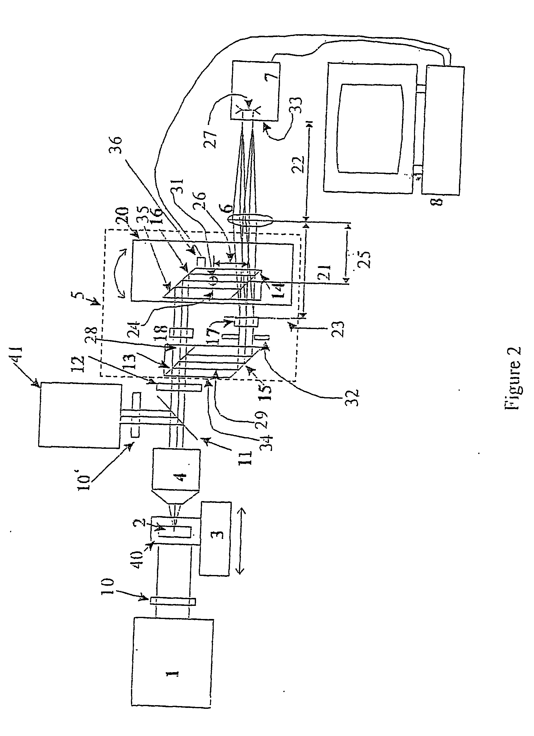
[0132]A second preferred embodiment of a microscope according to the present invention is illustrated in FIG. 2. In this second embodiment, the first beam splitter 13 and the second reflecting element 15 are parts of a first prism 34, while the second beam splitter 14 and the first reflecting element 16 are parts of a second prism 35.

[0133]Said prisms 34, 35 are special custom prisms made in bulky optical transparent materials. Those one are preferably constituted by two optical parts cemented together. The reflecting elements 15 and 16 are implemented at the total internal reflection faces of the prisms 34 and 35. The beam splitters 13, 14 are located at the boundary between two cemented optical parts.

[0134]The second prism 35 is placed on the rotation plate 20, as in the previous embodiment to equalize the two interferometric paths.

[0135]The second prism 35 is also slightly rotated by a piezoelectric transducer 36 driven by the computer 8 around a second independent rotation axis ...

third preferred embodiment

[0139]A third preferred embodiment provides another way to create the same effect as the one obtained with the wedge 17 and its complementary optical compensator 18 as used in the first and second embodiments disclosed hereabove. In this third embodiment, the wedge 17 and the flat 18 are not present and the mirror 15 is placed on rotation and / or translation means in such a way that equalization of the optical path is kept and that the light intensity distributions are kept identical and equally positioned in the front focal planes 23 and 24 of the focusing means 6.


PUM


Abstract

The present invention is related to a compact microscope able to work in digital holography for obtaining high quality 3D images of samples, including fluorescent samples and relatively thick samples such as biological samples, said microscope comprising illumination means (1,41) at least partially spatially coherent for illuminating a sample (2) to be studied and a differential interferometer (5) for generating interfering beams from said sample (2) on the sensor (33) of an electronic imaging device (7), said interferometer (5) comprising namely tilting means (17) for tilting by a defined angle one the interfering beams (28 or 29) relatively to the other, said tilting resulting into a defined shift (27) of said interfering beam on the sensor of the electronic imaging device (7), said shift (27) being smaller than spatial coherence width of each beam, said microscope being able to be quasi totally preadjusted independently from the samples so that minimum additional adjustments are required for obtaining reliable 3D images of samples.

Description

FIELD OF THE INVENTION[0001]The present invention relates to digital holographic microscopy.[0002]More particularly, the present invention concerns an improved digital holographic microscope and a process for obtaining with low temporal distortion high quality three-dimensional images of samples including fluorescence samples and thick samples.STATE OF THE ART[0003]The principle of interferometry has been set up for a long time.[0004]Digital holography and shearography correspond two different fields of interferometry.[0005]In shearography, a sample consisting in a diffusive structure and illuminated by a coherent beam creates a speckle field. This speckle field is interfering with itself after being shifted by a shearing distance. As the information about the sample is carried by the interfering speckle fields, the highly coherent illumination with a laser is mandatory.[0006]It results that shearography interferometers in general, and in particular the shearography interferometer d...

Claims


Application Information

Patent Timeline
Patent Type & Authority Applications(United States)
IPC IPC(8): G03H1/08G01B9/02G01B9/021G01B9/04G02B21/16G02B21/22G02B21/36
CPCG01B9/021G01B9/04G02B21/16G02B21/22G03H1/0443G03H1/0005G03H1/0866G03H2001/005G03H2001/0454G02B21/36G03H2222/24G03H1/0493
Inventor DUBOIS, FRANKYOURASSOWSKY, CATHERINE
Owner UNIV LIBRE DE BRUXELIES
Why Eureka
Try Eureka