Light-Source Holder, Illumination Device For Display Device, And Display Device

Inactive Publication Date: 2008-01-24
SHARP KK
View PDF4 Cites 18 Cited by
  • Summary
  • Abstract
  • Description
  • Claims
  • Application Information

AI Technical Summary

Benefits of technology

[0007] In order to overcome the problems described above, preferred embodiments of the present invention provide a ligh

Problems solved by technology

In such a case, backlash between the attached lamp clip and the bottom plate of the case is experienced, and thus,

Method used


Image

  • Light-Source Holder, Illumination Device For Display Device, And Display Device
  • Light-Source Holder, Illumination Device For Display Device, And Display Device
  • Light-Source Holder, Illumination Device For Display Device, And Display Device

Examples


first preferred embodiment

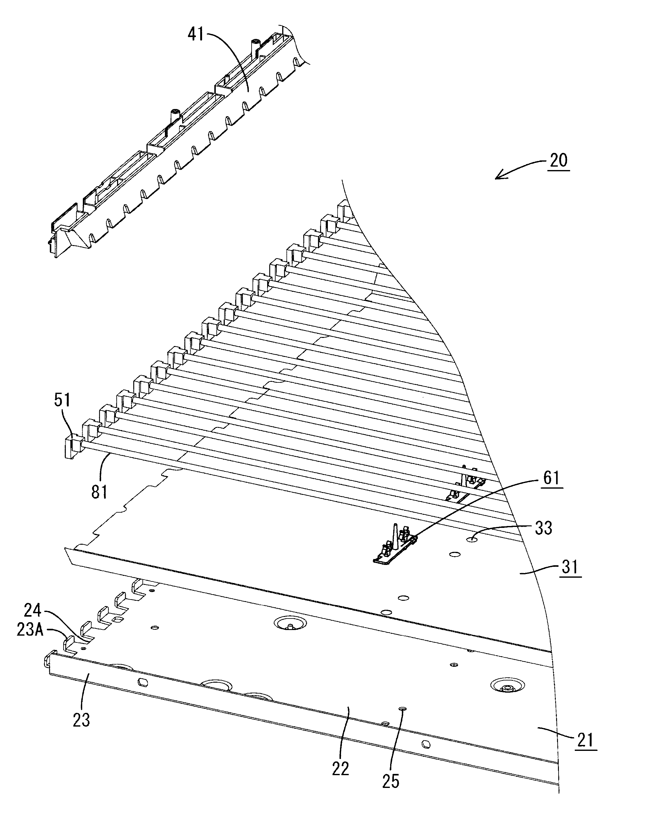
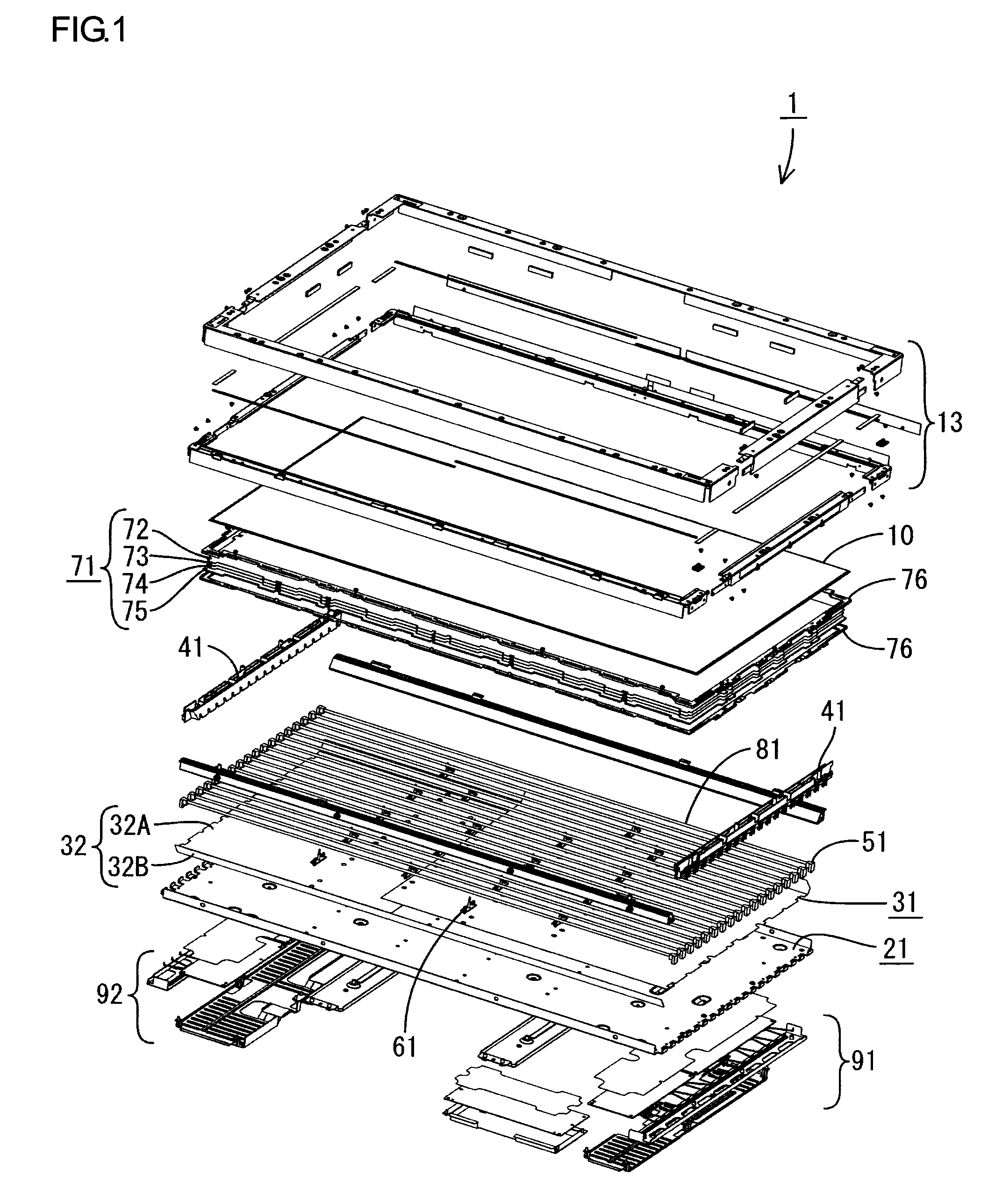
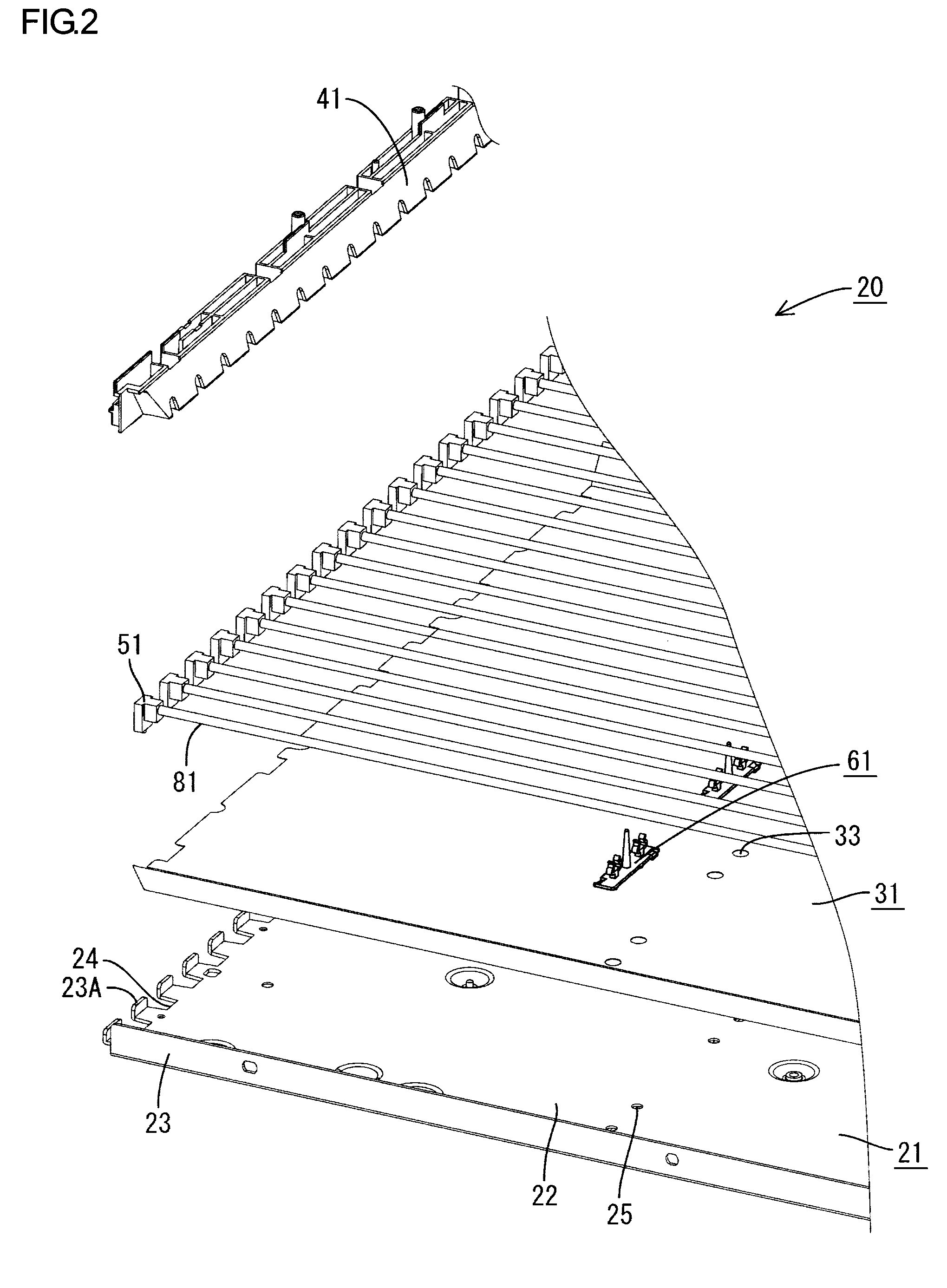
[0028] Hereinafter, a first preferred embodiment of the present invention will be described in detail with reference to FIGS. 1 to 7. FIG. 1 shows an exploded perspective view of the liquid crystal display 1 according to a preferred embodiment of the present invention (corresponding to the display device of the present invention). The liquid crystal display 1 includes a liquid crystal display panel 10 of a non-luminescent type having no self-luminous element (corresponding to the display panel according to preferred embodiments of the present invention), an optical member 71 disposed in the back surface side of the liquid crystal display panel 10, and a backlight unit 20 (corresponding to the illumination device for a display device of the present invention) adapted to be assembled from the back surface side of the liquid crystal display panel 10 and the optical member 71; these components are adapted to be held together in one piece by a bezel 13. Moreover, in the following descrip...

second preferred embodiment

[0046] Hereinafter, the second preferred embodiment of the present invention will be described in detail with reference to FIGS. 8 to 10. The lamp clip 101 of the present preferred embodiment includes a body part 102 having a substantially rectangular plate form as in the case of the first preferred embodiment, and the body part 102 is provided in its back and front surfaces with a clipping part 103, a pin 104, and a locking part 105 having a similar shape to those of the first preferred embodiment (FIG. 8).

[0047] In the body part 102, both ends in the long-side direction is inclined so as to progressively descend toward the back surface side (where the locking part 105 is provided) starting from a point slightly inside the edge of the short side, and this inclined part is provided as the plate spring part 106. The inclination of these plate spring parts 106 is adjusted such that its tip part (edge of short side) is located slightly closer to the back side than the projection end o...


PUM


Abstract

A lamp clip for holding a cold cathode tube onto a bottom plate part of a backlight case includes a body part adapted to be put into contact with the bottom plate part, a locking part protruding from the body part and being able to be locked onto the bottom plate part; and a plate spring part provided in the body part and adapted to bias the body part in a direction to be spaced apart from the bottom plate part. Upon assembling the lamp clip onto the bottom plate part, the body part is biased in a direction to be spaced apart from the bottom plate part due to the resilience of the plate spring part, thereby being locked in a state in which the locking face of the locking part is pressed against the peripheral margin of an insertion hole in the back surface of the bottom plate part. Thereby, it is possible to prevent backlash of the lamp clip with respect to the bottom plate part and prevent chattering sound from being generated. Further, a pair of plate spring parts are provided at opposed positions on either side of the locking part and projected in opposite directions to each other. This makes it possible to support the body part with good balance at both sides and fix it onto the bottom plate part without inclination.

Description

BACKGROUND OF THE INVENTION [0001] 1. Field of the Invention [0002] The present invention relates to a light-source holder, an illumination device for a display device, and a display device. [0003] 2. Description of the Related Art [0004] In a non-luminescent display device such as a liquid crystal display device, a backlight unit is provided at the back surface of a panel so as to illuminate it. See, for example, Japanese Patent Laid-Open No. 2001-210126. This backlight unit is configured such that a plurality of light sources such as cold cathode tubes are arranged in parallel and contained inside a case which is formed into a shallow pan shape. [0005] These light sources are fixed to the bottom plate of the case with a light-source holder, such as a lamp clip formed of resin, etc. This lamp clip is configured such that in its body part there is provided on a surface opposed to the case bottom plate an engaging part for engaging with the case, and on the opposite surface a clippin...

Claims


Application Information

Patent Timeline
IPC IPC(8): F21S8/00
CPCG09F9/307G02F1/133604
Inventor AOKI, KENTOROHOKITSU, MOTOAKI
Owner SHARP KK
Why Eureka
Try Eureka