Moulding device for the manufacture of thermoplastic containers

Inactive Publication Date: 2008-01-24
SIDEL PARTICIPATIONS SAS
View PDF6 Cites 8 Cited by
  • Summary
  • Abstract
  • Description
  • Claims
  • Application Information

AI Technical Summary

Benefits of technology

[0023]There is, therefore, on the part of the operators of such moulding installations, an urgent requirement that these disadvantage

Problems solved by technology

These numerous drill holes and machinings mechanically weaken these components which, moreover, are subjected to very high mechanical stresses during blowing.
Above all, another major disadvantage is that, during each remounting, it is necessary to repeat the settings of the return and abutment prestress for each of the means in question.
It becomes clear that the setting of the abutment means systematically disturbs the setting of the elastic return means for compensation, thus making it necessary to repeat these settings alternately.
Furthermore, the springs made of synthetic material which are used in the moulding devices of cold-cycle operation lose their elasticity progressively and finally become slack, thus making it necessary to replace them regularly.
Practice shows, however, that, during the remounting operations, washers may be remounte

Method used


Image

  • Moulding device for the manufacture of thermoplastic containers
  • Moulding device for the manufacture of thermoplastic containers
  • Moulding device for the manufacture of thermoplastic containers

Examples


Example

DETAILED DESCRIPTION OF THE DRAWINGS

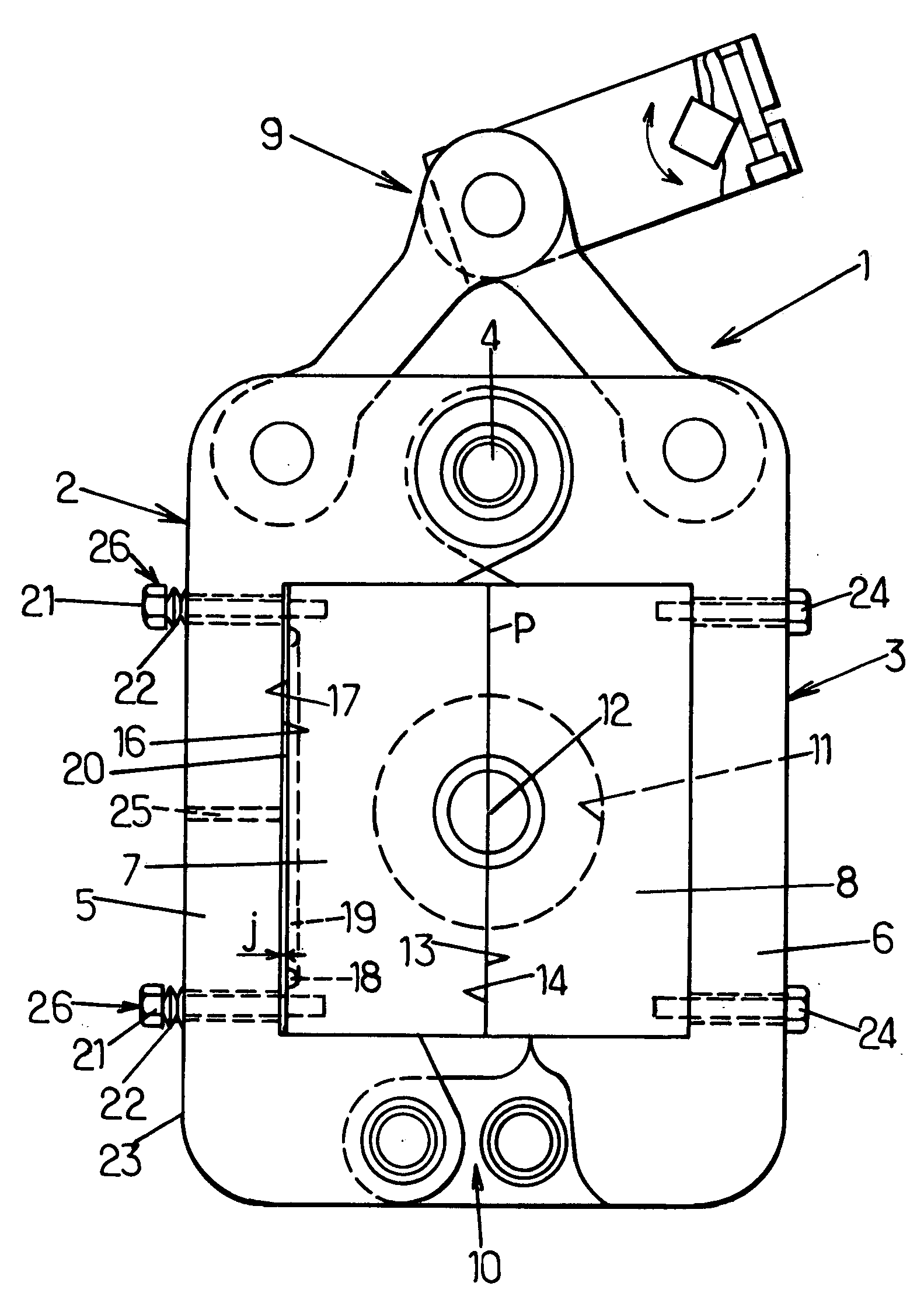
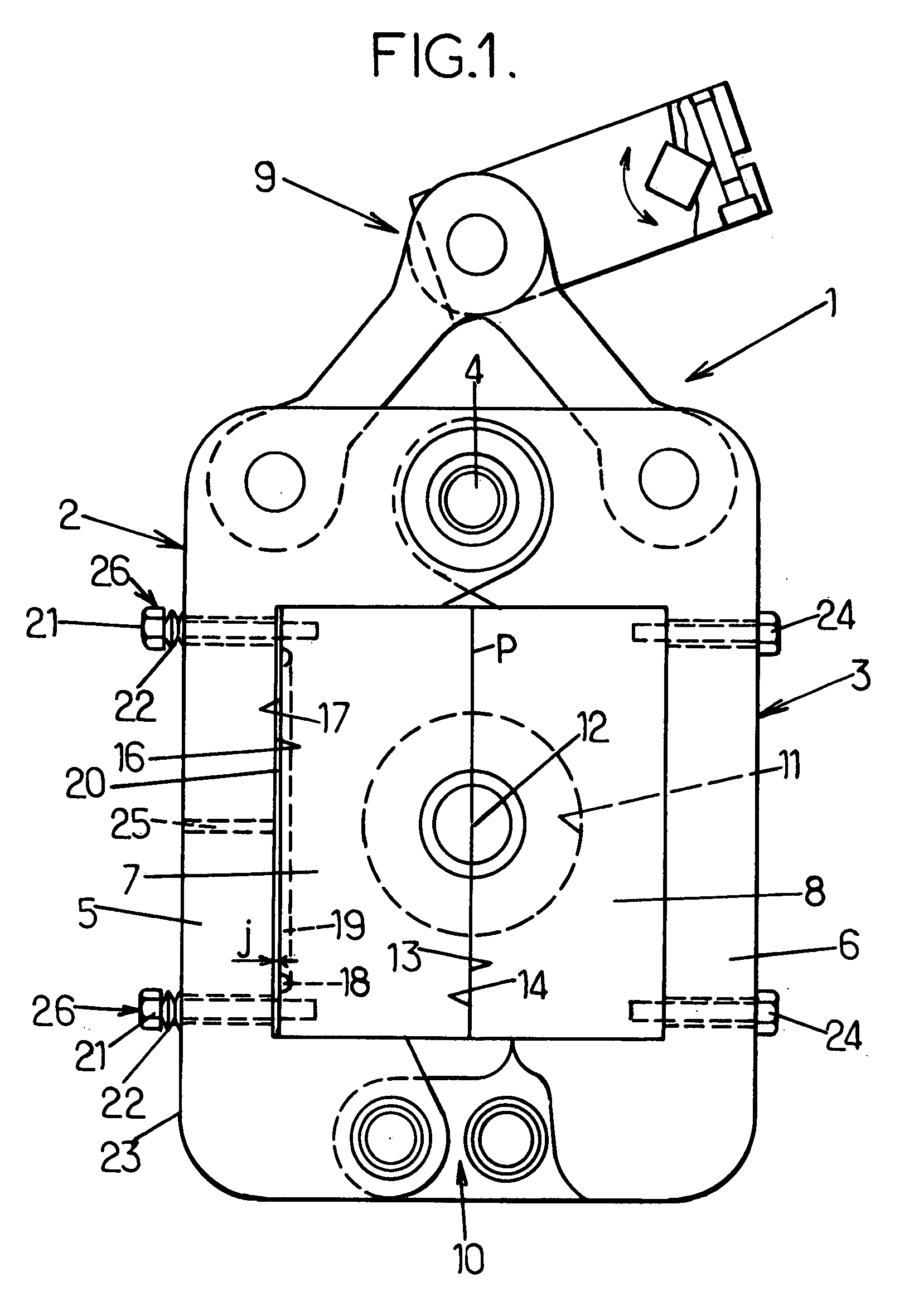
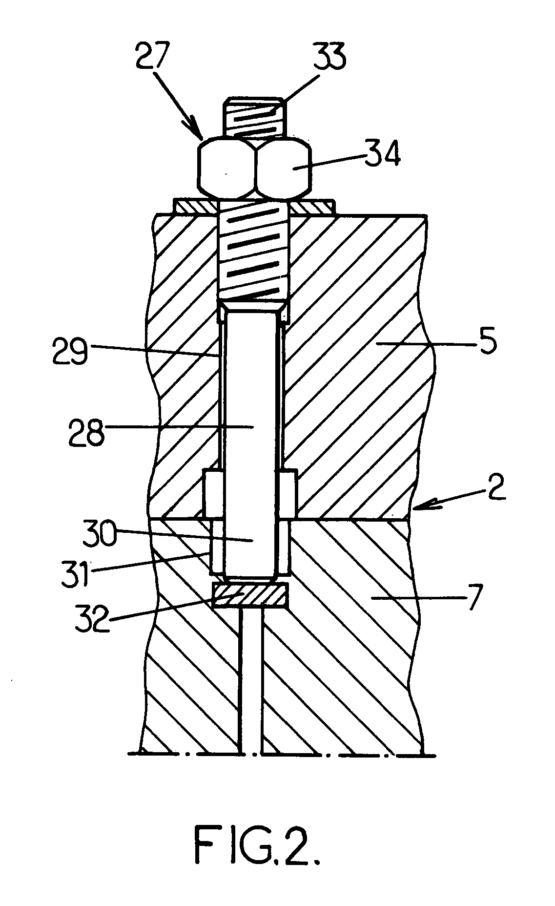
[0044]Reference will first be made to FIG. 3A in which the same reference numerals as in FIGS. 1 and 2 have been retained in order to designate the same members. For the sake of clarity, FIG. 3A shows only a portion of the support 5 and a corresponding portion of the mould block 7.

[0045]According to the invention, the elastic return means and the abutment means are equal in number and are combined respectively in pairs in the form of unitary assemblies. FIG. 3A illustrates such a unitary assembly, designated as a whole by the reference numeral 35, which is designed as follows.

[0046]A bore 36 passes through the support 5 on the outside of the compensating chamber (not shown in FIG. 3A) and substantially perpendicularly to the parting plane and issues in front of the mould block 7; this bore 36 is internally threaded at least over part of its length, especially at 37 in the vicinity of its orifice, as shown in FIG. 3A.

[0047]A pin 38 is engaged coaxi...


PUM

PropertyMeasurementUnit
Displacementaaaaaaaaaa

Abstract

A device for the moulding of thermoplastic containers by blowing comprises a mould (1) with two half-moulds (2, 3), each having a support (5, 6) and a mould block (7, 8) between which, in one half-mould, a compensating chamber (20) is defined, with elastic return means (26) and abutment means (27) being interposed, which are combined in unitary assemblies (35) each comprising: a bore (36) passing through the support and receiving a pin (38) having one end (39) fastened to the mould block and a first radial shoulder (40) against which bears the end (E) of a sleeve (46) screwed in the bore and having an outer head (47) capped by an axially displacaeable housing (49), with the elastic return means being interposed, which are preloaded by a nut (53) screwed on the free end of the pin against a second radial shoulder (54) of the pin, at the same time pushing the housing.

Description

FIELD OF THE INVENTION[0001]The present invention relates in general terms to the field of the moulding of containers, especially of bottles, made from thermoplastic, such as PET, by the blowing or draw-blowing of heated preforms, and it relates more specifically to improvements made to the devices for the moulding of containers, especially of bottles, made from thermoplastic, such as PET, by the blowing or draw-blowing of heated preforms, said devices comprising at least one mould with a compensating chamber.[0002]More precisely, the invention relates to improvements made to the devices for the moulding of containers, especially of bottles, made from thermoplastic, such as PET, by the blowing or draw-blowing of heated preforms, which moulding devices comprise at least one mould comprising at least two half-moulds respectively comprising two supports and two mould blocks defining a parting plane in the closing position of the mould, a leak-tight compensating chamber being defined be...

Claims


Application Information

Patent Timeline
IPC IPC(8): B29C49/36
CPCB29C33/26B29C49/06B29C49/36B29C49/48B29L2031/712B29C2049/4856B29C2049/4864B29K2067/00B29C49/56B29C2049/5633B29C2049/5635B29C2049/5664B29C2949/0715
Inventor BIANCHINI, CEDRICTOUTOUX, ALEXANDRE
Owner SIDEL PARTICIPATIONS SAS
Why Eureka
Try Eureka