Collapsible Mobile Radio Device

Inactive Publication Date: 2008-01-24
PANASONIC CORP
View PDF3 Cites 12 Cited by
  • Summary
  • Abstract
  • Description
  • Claims
  • Application Information

AI Technical Summary

Benefits of technology

[0021] According to the present invention, the antenna current in the thin antenna built in the case can be distributed to a position that is away from the human body, and also a polarization can be optimized to a speaking condition. Therefore, the folding type portable radio equipment capable of reducing a local mean SAR and ensuring a high antenna gain can be provided.

Problems solved by technology

However, when a thickness of the folding cellular phone is reduced, there is a problem such that the antenna performance is degraded because the antenna comes closer to the user.
In addition, when the folding cellular phone is reduced in thickness in this manner, there is another problem such that it is difficult to reduce a local means SAR (Specific Absorption Rate).

Method used


Image

  • Collapsible Mobile Radio Device
  • Collapsible Mobile Radio Device
  • Collapsible Mobile Radio Device

Examples


first embodiment

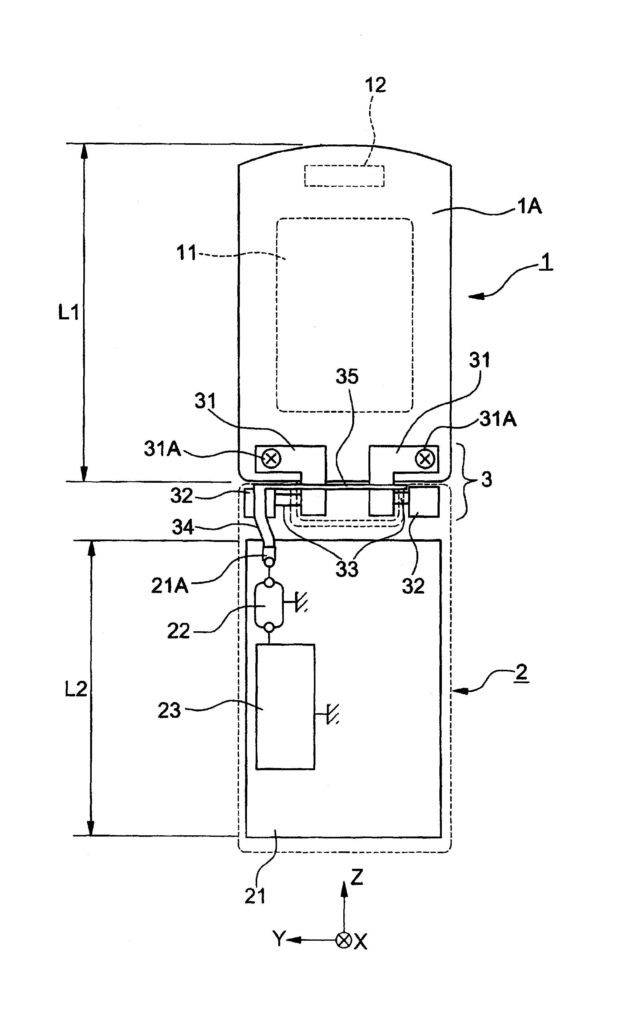
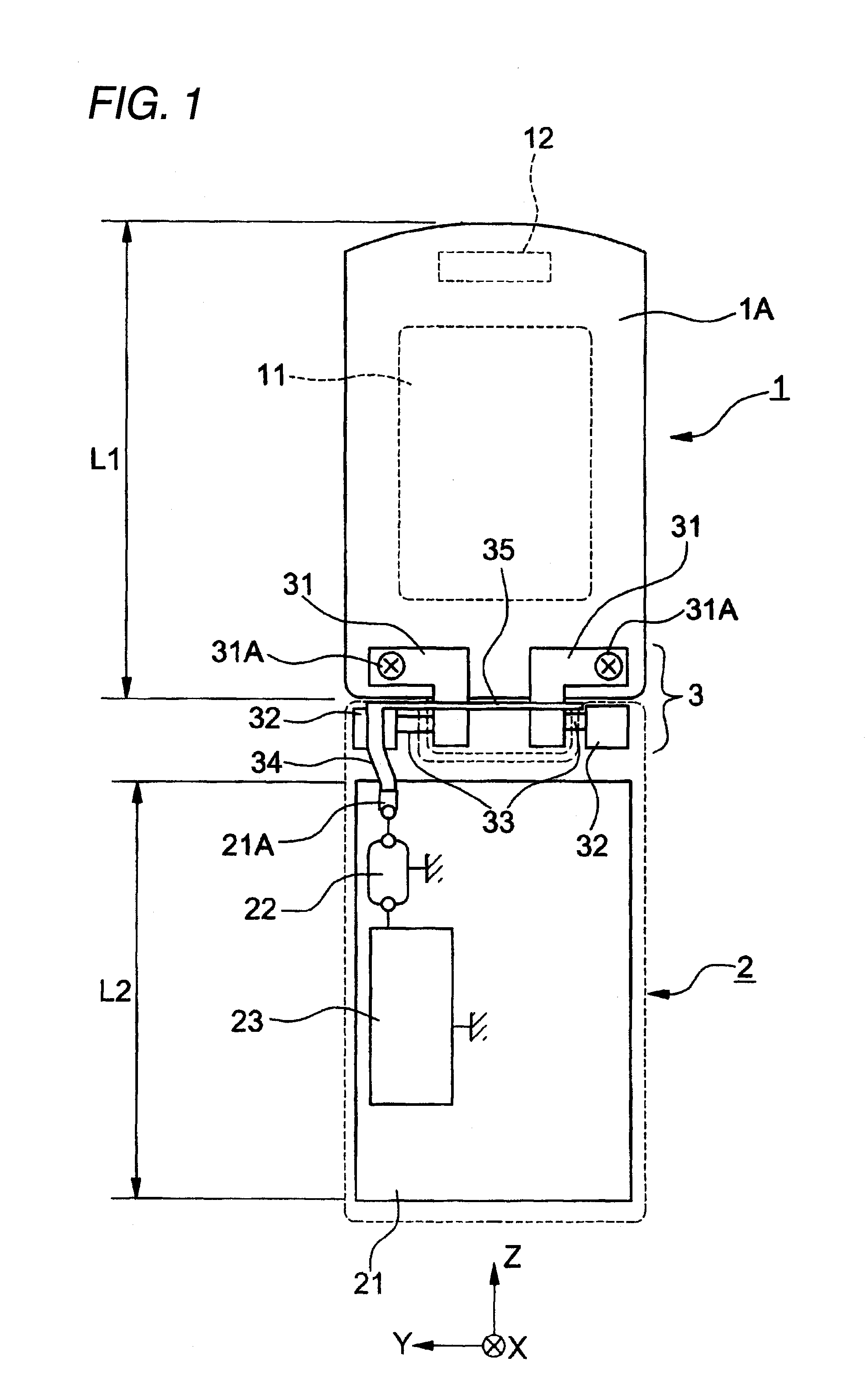
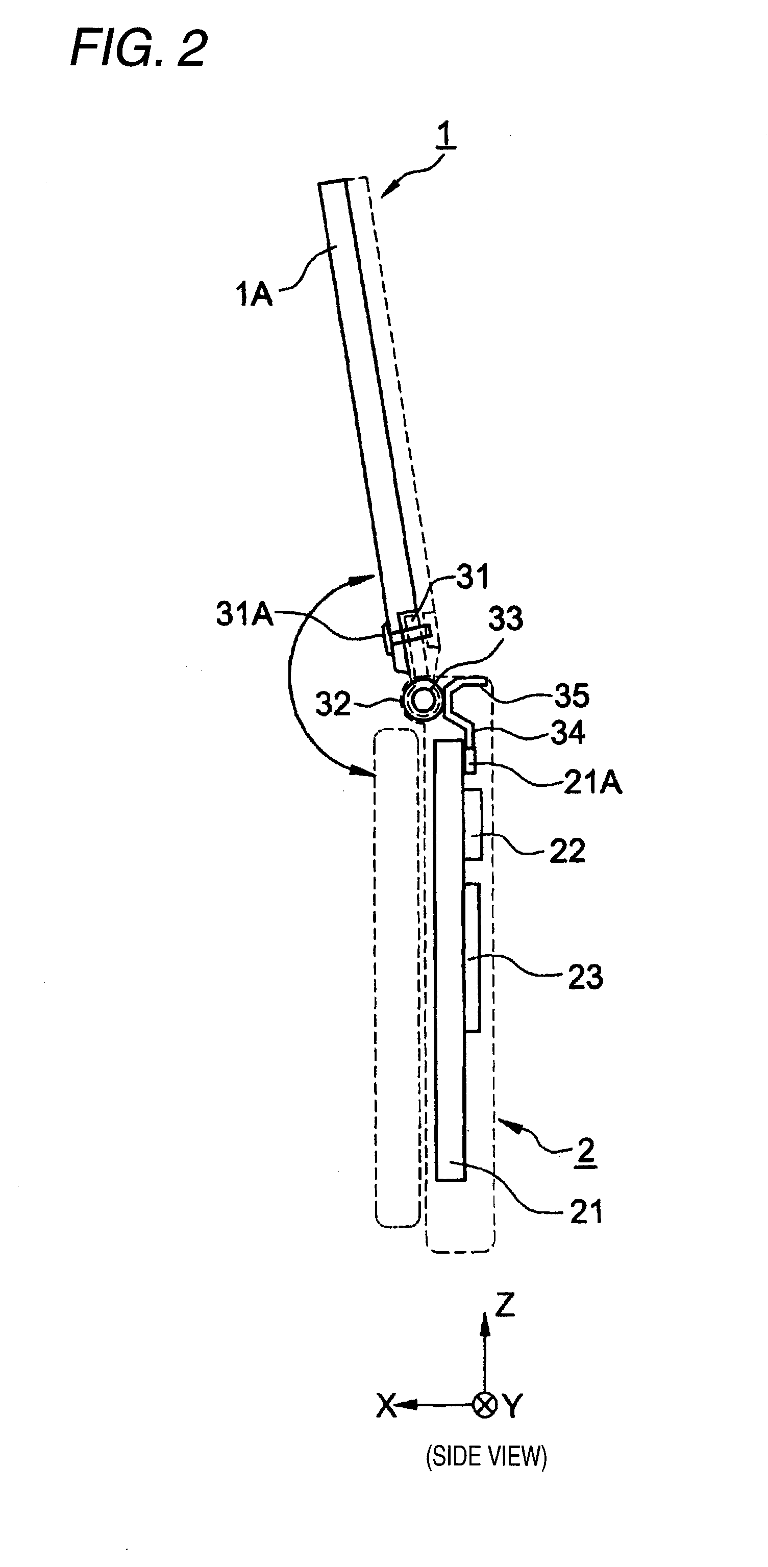
[0062]FIG. 1 is a front view of a folding type portable radio equipment according to a first embodiment of the present invention, FIG. 2 is a side view of the folding type portable radio equipment of the same, and FIG. 3 is a perspective view of the folding type portable radio equipment of the same.

[0063] As shown in these Figures, the folding type portable radio equipment of the present embodiment has a foldable configuration in which a first case (referred to as an “upper case 1” hereinafter) and a second case (referred to as a “lower case 2” hereinafter) are joined by a hinge portion 3 (one-shaft hinge structure), and can take two operation modes of an opened mode and a closed mode by turning either of the upper case and the lower case 2 around the hinge portion 3.

[0064] The upper case 1 has a display portion 11 and an opening portion 12 for an earpiece portion on a surface (inner surface) in the (+) X-axis direction. Further, operation keys (not shown) are arranged on a surfac...

second embodiment

[0090] Next, a second embodiment of the present invention will be explained in detail with reference to FIG. 10 hereunder.

[0091]FIG. 10 is a perspective view showing a folding type portable radio equipment according to the present embodiment when viewed from the rear surface side. In this case, the same reference symbols as those in FIG. 1 show the same constituent elements and their detailed explanations will be omitted herein.

[0092] In the folding type portable radio equipment of the present embodiment, as shown in FIG. 10, a conductive metal element 25 connected electrically to the hinge portion 32 that acts as the feeding portion is constructed by two conductive metal elements having a different length respectively, i.e., a first conductive metal element 25A (length L5) and a second conductive metal element 25B (length L6).

[0093] The conductive metal element 25 is constructed integrally with the feeding metal 34, for example. In the present embodiment, the conductive metal el...


PUM


Abstract

A conductive metal frame and a first hinge portion fitted onto an upper case are connected electrically, first and second hinge portions are joined to turn on a rotating shaft, and the first and second hinge portions and the rotating shaft are formed of a conductive metal and conducted electrically via respective contact points. The second hinge portion as the feeding portion is connected to a matching circuit on a circuit board, and one end of a conductive metal element having a predetermined length is connected to the second hinge portion to have an electrical conduction thereto and the other end of the conductive metal element is opened. The conductive metal element is arranged in parallel with a direction orthogonal with a longitudinal direction of a lower case, and is arranged near a surface on the opposite side to the surface on which the operation keys are arranged.

Description

TECHNICAL FIELD [0001] The present invention relates to a folding type portable radio equipment capable of maintaining a high antenna performance in a speaking condition. BACKGROUND ART [0002] The spread of the cellular phone is notable recently. In particular, the folding cellular phone in which the upper and lower cases are joined by the hinge portion to open / close becomes widespread. This folding cellular phone has normally two operation modes of an opened mode and a closed mode. Thus, this folding cellular phone has two advantages, a convenience that a display screen to be looked can be widened when the phone is used in an opened state (opened mode) and an easy-carry quality that the cellular phone can be folded up-into a compact form when the phone is used in a closed state (closed mode). [0003] Further, a reduction in thickness is required of the folding cellular phone nowadays. However, when a thickness of the folding cellular phone is reduced, there is a problem such that th...

Claims


Application Information

Patent Timeline
IPC IPC(8): H04M1/00
CPCH01Q1/243H01Q9/28H04M1/0216H01Q9/32H01Q9/42H01Q9/30
Inventor KOBAYASHI, HIROAKIKOSHI, MASASHIYAMADA, KENICHISAITO, YUTAKA
Owner PANASONIC CORP
Why Eureka
Try Eureka