Sacral or iliac cross connector

a cross-connector and iliac technology, applied in the field of implantable devices, can solve the problems of immobility of patients, limited ability of current external braces to correct deformed spines, severe restrictions, etc., and achieve the effect of facilitating positioning of the second spinal fixation elemen

Inactive Publication Date: 2008-01-24
DEPUY SPINE INC (US)
View PDF15 Cites 190 Cited by
  • Summary
  • Abstract
  • Description
  • Claims
  • Application Information

AI Technical Summary

Benefits of technology

[0013]Exemplary methods for anchoring a spinal fixation element to a patient's sacrum or ilium are also provided, and in one embodiment a method can include anchoring a cross member to bone, sliding a connector head along the cross member, positioning a spinal fixation element within the connector head, and locking the spinal fixation element within the connector head to thereby lock the connector head in a fixed position relative to the cross member. The method can also include positioning a second spinal fixation element within a second connector disposed on the c...

Problems solved by technology

These devices, however, resulted in severe restriction and in some cases immobility of the patient.
Furthermore, current external braces have limited ability to correct the deformed spine and typically only prevent progression of the deformity.
As a result, surgeons are always concerned about the possibility of the implant loosening or the bone screws pulling out of the bone, especially where the system is anchored to the sacrum or ilium.
The sacrum and ilium are usually of poor bone quality, consisting primarily of cancellous bone with thin cortical bone, magnifying the problem when fixatio...

Method used


Image

  • Sacral or iliac cross connector
  • Sacral or iliac cross connector
  • Sacral or iliac cross connector

Examples


Embodiment Construction

[0026]Certain exemplary embodiments will now be described to provide an overall understanding of the principles of the structure, function, manufacture, and use of the devices and methods disclosed herein. One or more examples of these embodiments are illustrated in the accompanying drawings. Those of ordinary skill in the art will understand that the devices and methods specifically described herein and illustrated in the accompanying drawings are non-limiting exemplary embodiments and that the scope of the present invention is defined solely by the claims. The features illustrated or described in connection with one exemplary embodiment may be combined with the features of other embodiments. Such modifications and variations are intended to be included within the scope of the present invention.

[0027]The present invention generally provides devices and methods for connecting a spinal fixation element to bone in a patient's spinopelvic region. The devices and methods have particular...


PUM


Abstract

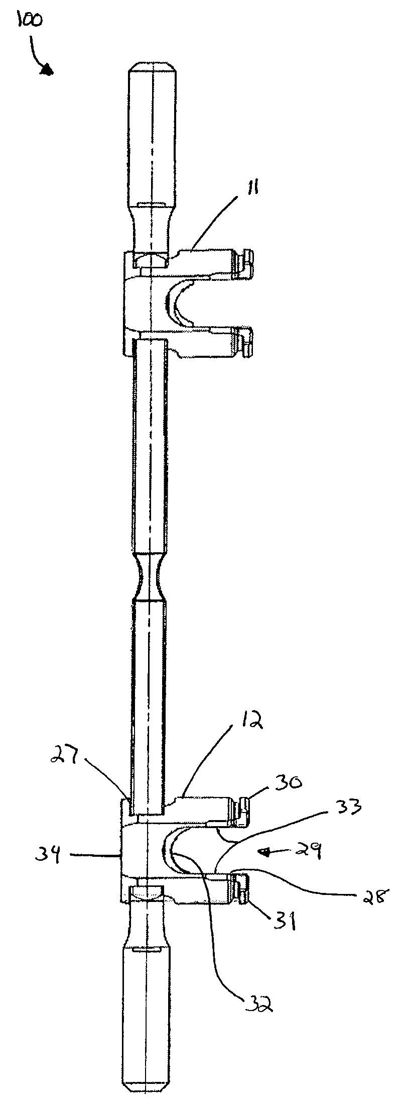
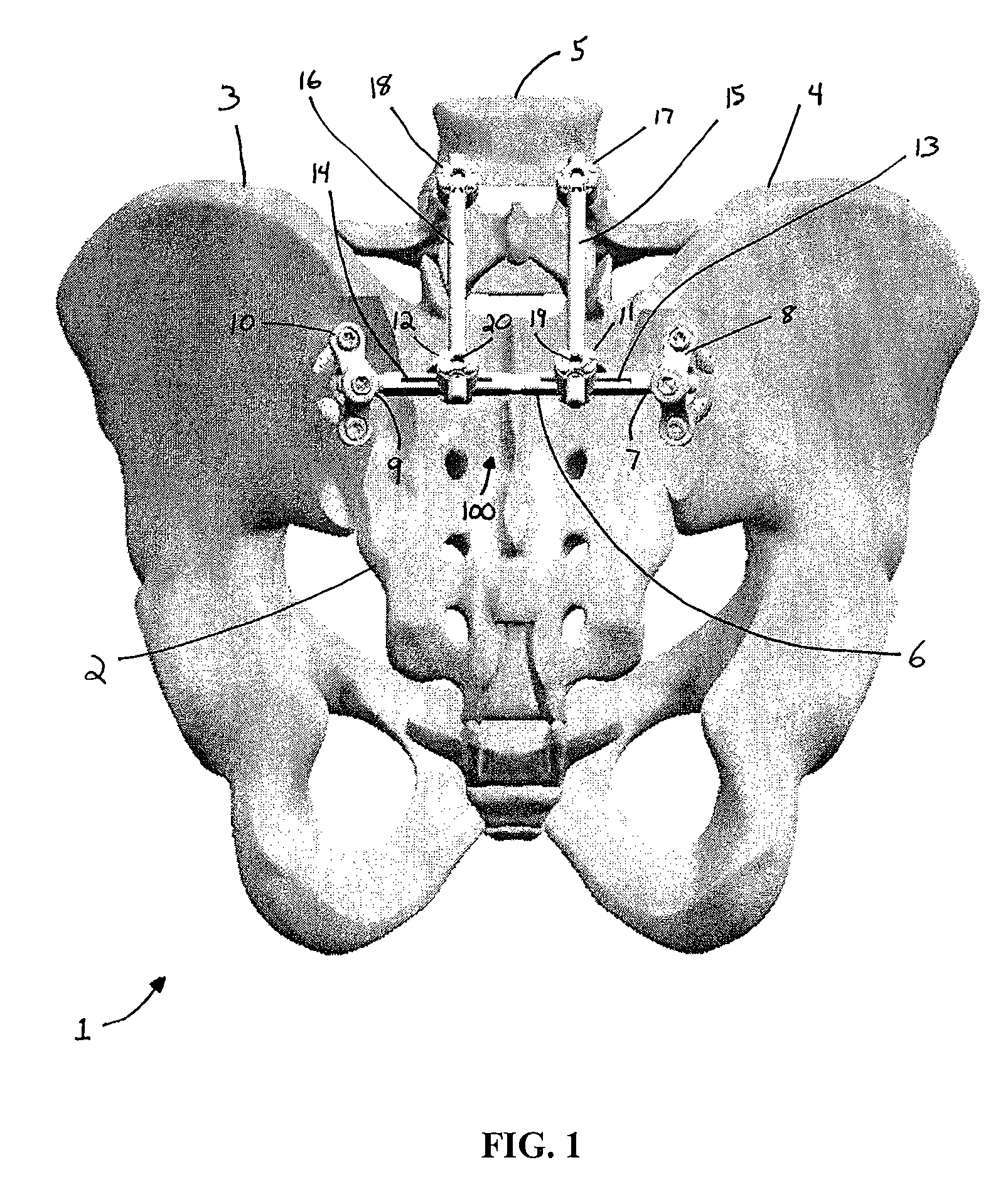
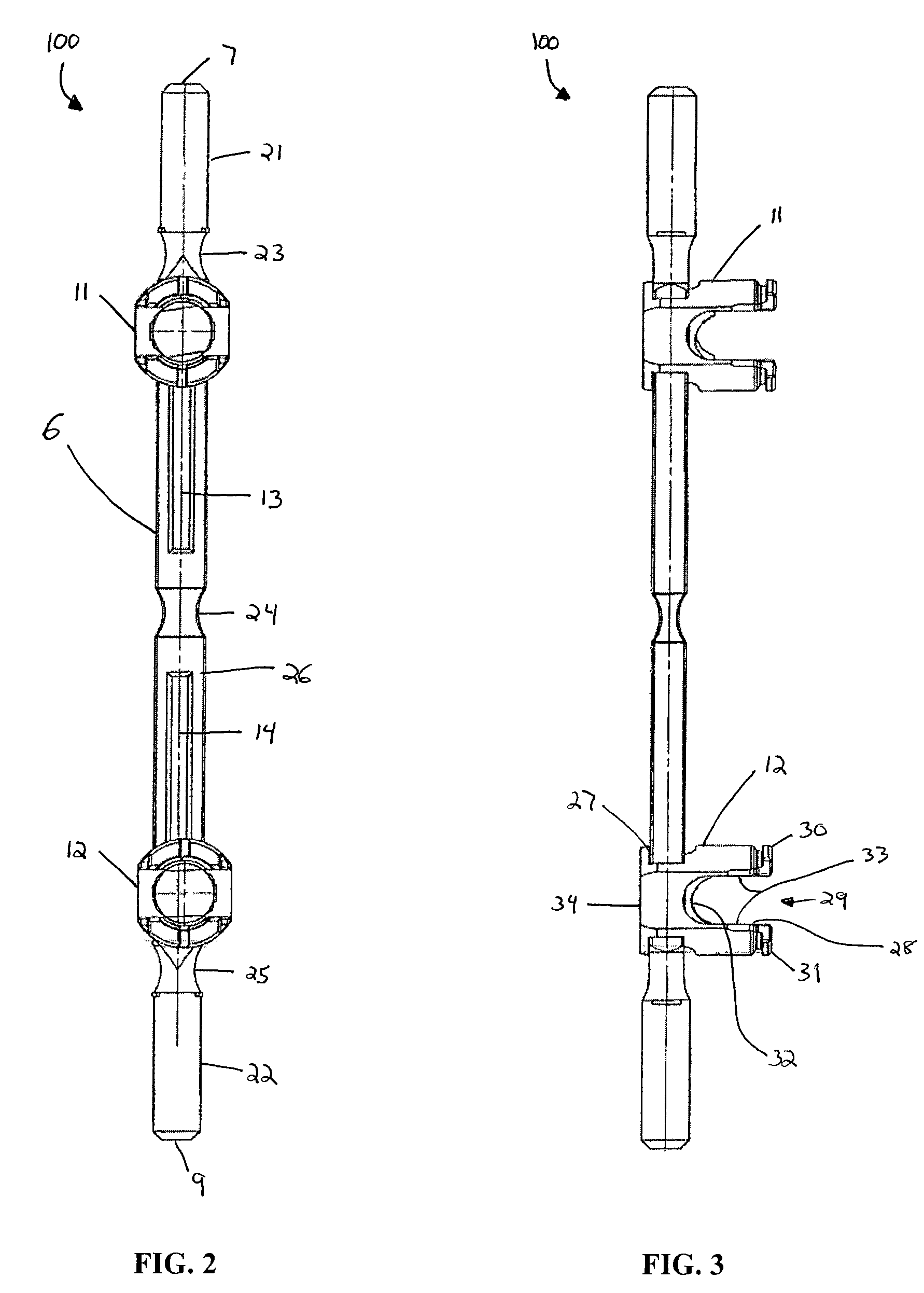
Implantable devices and methods for correcting spinal deformities or degeneration are disclosed. The devices and methods have particular application in the spinopelvic region and on the sacrum or ilium. In one embodiment, a cross connector is provided and can include a cross member with a connector head slidably disposed thereon. The cross member can be adapted for attachment to one or more anchoring elements, and the sliding connector head can include a first receiving portion defined by an opening through the connector head for receiving the cross member, and a second receiving portion defined by a recess between first and second opposed arms for receiving a spinal fixation element, such as a spinal rod. A guide channel can optionally be provided on the cross member for guiding the movement of the sliding connector head. In other embodiments, the device can include a locking mechanism for locking a spinal fixation element within the connector head, and for securing the connector head in place on the cross member.

Description

FIELD OF THE INVENTION[0001]The present invention relates to implantable devices and methods for correcting spinal deformities or degeneration, and for connecting a spinal fixation element to bone.BACKGROUND OF THE INVENTION[0002]Spinal deformities, which include rotation, angulation, and / or curvature of the spine, can result from various disorders, including, for example, scoliosis (abnormal curvature in the coronal plane of the spine), kyphosis (backward curvature of the spine), and spondylolisthesis (forward displacement of a lumbar vertebra). Other causes of an abnormally shaped spine include trauma and spinal degeneration with advancing age. Early techniques for correcting such deformities utilized external devices that applied force to the spine in an attempt to reposition the vertebrae. These devices, however, resulted in severe restriction and in some cases immobility of the patient. Furthermore, current external braces have limited ability to correct the deformed spine and ...

Claims


Application Information

Patent Timeline
IPC IPC(8): A61F2/30
CPCA61B17/7041A61B17/7043A61B17/7055A61B17/7049A61B17/7044
Inventor GUPTA, MUNISHCHAO, NAM T.SYLVIA, ROSS
Owner DEPUY SPINE INC (US)
Why Eureka
Try Eureka