Electronic circuit comprising a test mode secured by insertion of decoy data in the test chain, associated method

a technology of electronic circuits and decoy data, applied in the field of synchronous electronic integrated circuits, can solve the problem that the decoy data cannot be used to obtain information on the internal data of the circui

Active Publication Date: 2008-01-24
STMICROELECTRONICS SRL
View PDF3 Cites 9 Cited by
  • Summary
  • Abstract
  • Description
  • Claims
  • Application Information

AI Technical Summary

Benefits of technology

[0018]The electronic circuit in accordance with the invention can be distinguished from prior art methods in that it also comprises the following steps. A detection step for the production of a state signal representing a state of initialization of a first set of configurable cells. A switching step for the connection of the test input of each configurable cell of a second set of configurable cells to an output of a decoy data generator as a function of the state signal. The switching step may be executed in parallel with the propagation step during one or more periods of the data propagation signal, and then a new chaining step is performed.

Problems solved by technology

Decoy data cannot be used to obtain information on the internal data of the circuit.

Method used


Image

  • Electronic circuit comprising a test mode secured by insertion of decoy data in the test chain, associated method
  • Electronic circuit comprising a test mode secured by insertion of decoy data in the test chain, associated method
  • Electronic circuit comprising a test mode secured by insertion of decoy data in the test chain, associated method

Examples


Embodiment Construction

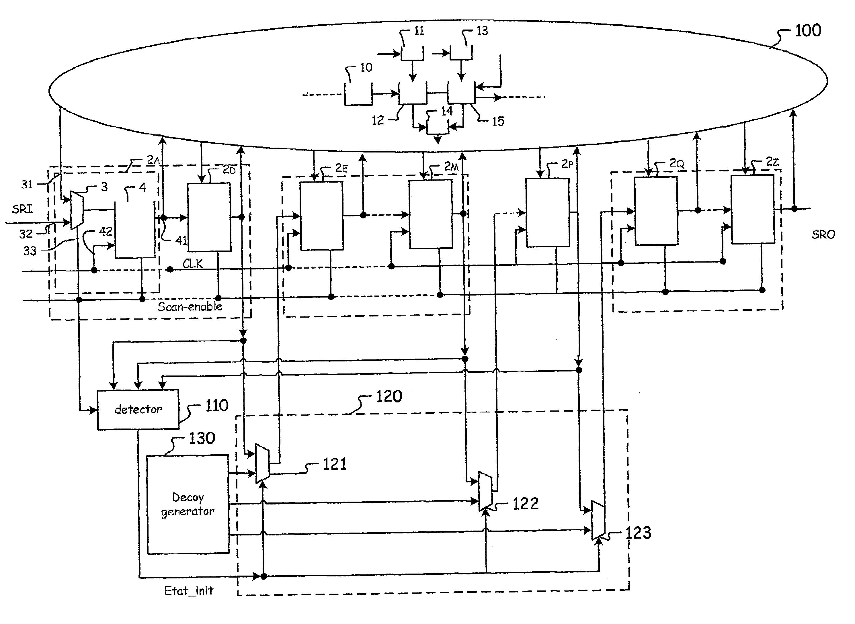
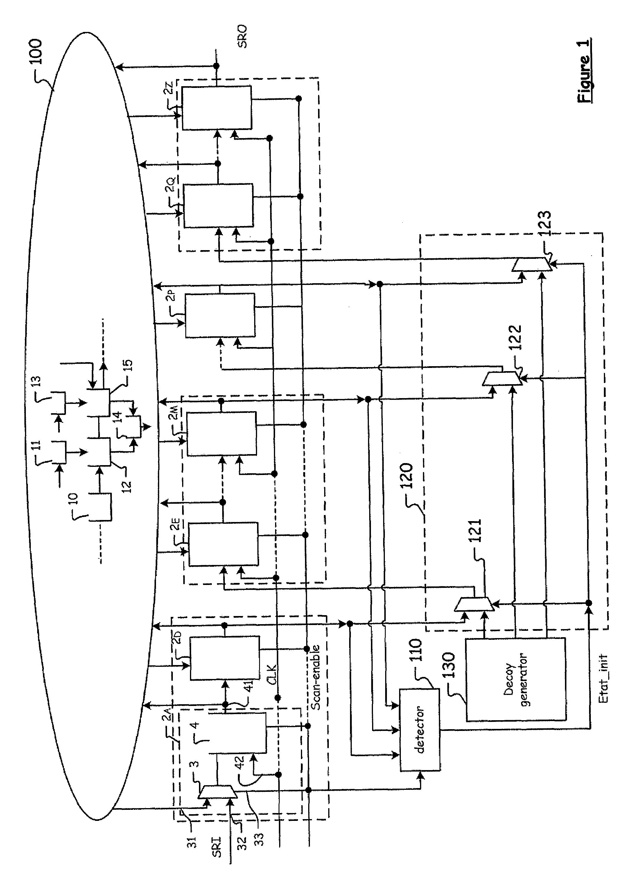
[0022]FIGS. 1 and 2 illustrate two examples of the electronic circuit. The circuit of FIG. 1 is an integrated circuit comprising a logic circuit 100 comprising a plurality of logic cells 10 to 15. The circuit i also has configurable cells 2a, . . . , 2d, 2e, 2m, . . . , 2q, . . . , 2z, capable of being connected to the logic cells 10 to 15 to form at least one functional circuit (such as a shift register, state machine, etc.), capable of being connected to one another to form a test shift register. They are also capable of receiving control signals, especially a chaining command signal SCAN_ENABLE and a data propagation signal CLK to write data to the configurable cells or to read data in these cells.

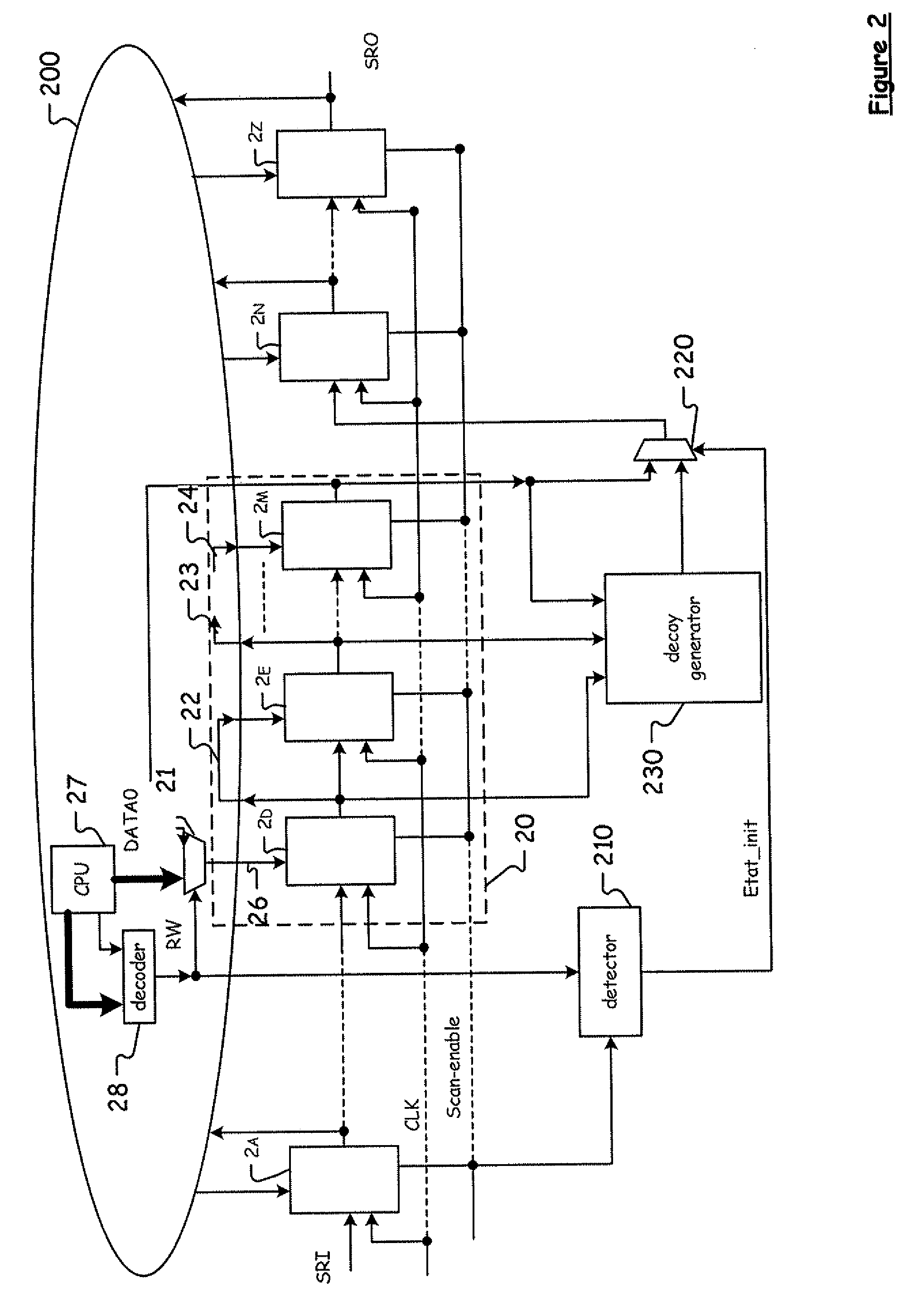
[0023]In the more concrete example of FIG. 2, the logic circuit 200 comprises a multiplexer 21 and linking means or connections 22, 23, 24, 25, 26 laid out so that, in the standard operating mode of the electronic device, when the signal SCAN_ENABLE is inactive, the configurable cells 2...


PUM


Abstract

An electronic circuit includes configurable cells each having a test input and an output. The configurable cells are connected to one another in a chain in a predefined order via their test input and their output to form a test register based on receiving a chaining command signal. The electronic circuit also includes a detection circuit activated by the chaining command signal to produce a state signal representing a state of initialization of a first set of configurable cells A multiplexing circuit selectively connects the test input of each configurable cell to a second set of the configurable cells either to the output of a preceding configurable cell or to an output of a decoy data generator based on the state signal.

Description

FIELD OF THE INVENTION [0001]The invention relates to synchronous electronic integrated circuits provided with combinatorial logic circuits, flip-flop circuits and test circuits.[0002]More specifically, the invention relates to an electronic circuit comprising configurable cells, with each cell comprising a test input and an output. The configurable cells are connected to one another in a chain to form a test register based on receiving a chaining command signal indicating a test mode for the electronic circuit.BACKGROUND OF THE INVENTION [0003]The configurable cells further comprise functional inputs, and when they do not receive a chaining command signal, the configurable cells are connected by their functional inputs and their outputs to logic cells with which they cooperate to form one or more logic circuits of the electronic circuit. This is a standard operating mode of the electronic circuit.[0004]There are well-known procedures for verifying that the functional elements of an...

Claims


Application Information

Patent Timeline
Patent Type & Authority Applications(United States)
IPC IPC(8): G01R31/28
CPCG01R31/318555G01R31/31719
Inventor BANCEL, FREDERICHELY, DAVID
Owner STMICROELECTRONICS SRL
Why Eureka
Try Eureka