Eureka AIR delivers breakthrough ideas for toughest innovation challenges, trusted by R&D personnel around the world.

Medicine inhaler and medicine ejection method

a technology of medicine inhaler and ejection device, which is applied in the direction of valve operating means/release devices, lighting and heating apparatus, heating types, etc., can solve the problems of small volume of bubbles to be produced, large variation in the quantity of medicine capable of being inhaled, and the volume of ejection liquid droplets tends to decrease, so as to achieve the effect of accurate dose of medicine, constant rate, and efficient inhalation

Inactive Publication Date: 2008-01-31
CANON KK
View PDF9 Cites 26 Cited by
  • Summary
  • Abstract
  • Description
  • Claims
  • Application Information

AI Technical Summary

Benefits of technology

[0012]An object of the present invention is to provide a medicine ejection device which can make the dose of medicine more accurate to enable a medicine to be efficiently inhaled, under any fluctuations of environmental conditions upon inhalation of the medicine. That is, the present invention provides a medicine ejection device for allowing a medicine with a desired droplet diameter to be inhaled at a constant rate.
[0015]Fluctuations of the quantity of the liquid medicine to be ejected or fluctuations of the total amount of the liquid medicine having been ejected and having the desired droplet diameter, which are caused by changes in an open-air environment during use of the device or changes in the state of the medicine, are corrected to enable the user to inhale the medicine in an accurate dose conforming to prescription. As a result, any mental and physical load can be lessened and the medicine can surely be sent to the lungs in an effective dose to enable the medicine to be effectively administered.

Problems solved by technology

The above conventional medicine ejection device has a problem in that the quantity of a medicine capable of being inhaled may greatly change depending on open-air environmental conditions (such as temperature, humidity and atmospheric pressure) during use of the device and on the condition of the medicine.
First, in the case of a liquid medicine, viscosity increases as the temperature of the liquid drops, and hence the volume of ejection liquid droplets tends to decrease.
In particular, in the system in which the liquid is ejected by producing air bubbles with a heater, if the liquid comes to have a low temperature, thus has a high viscosity, the volume of bubbles to be produced may become small or it becomes difficult to generate bubbles.
If the open air comes to have a low temperature, it inevitably affects the medicine temperature.
Also, as a factor other than that, it takes a time to raise the temperature of an ejection head at the initial stage of an ejection operating period of the ejection head, and hence the head comes to have poor ejection performance especially at the initial stage of the ejection operating period, resulting in a decrease in the total amount of liquid droplets to be ejected.
In this connection, if the liquid droplets come to have too small a diameter, they are inevitably extracorporeally discharged with the user's exhaled air.
As a result, the user can not inhale the medicine in a desired quantity.
Thus, there are circumstances where use conditions are so varied that it is difficult to make the dose of medicine constant.

Method used


Image

  • Medicine inhaler and medicine ejection method
  • Medicine inhaler and medicine ejection method
  • Medicine inhaler and medicine ejection method

Examples


example 1

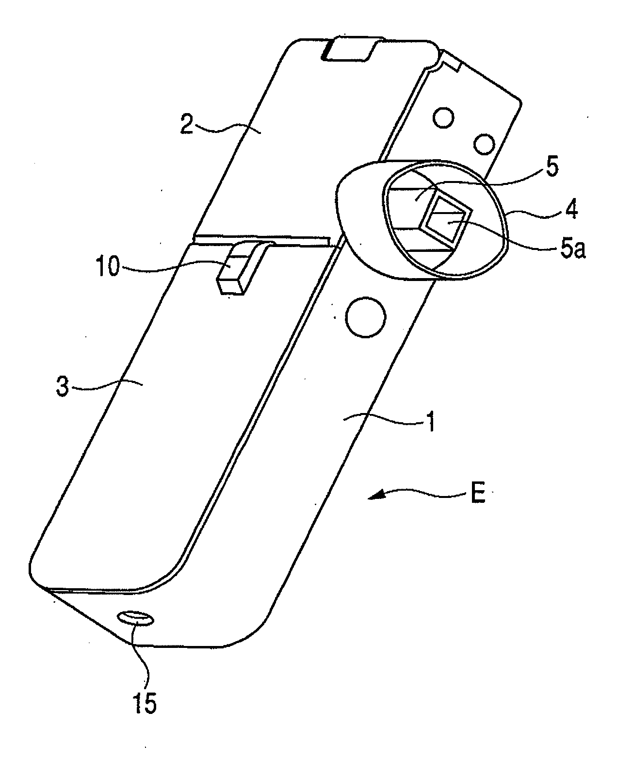
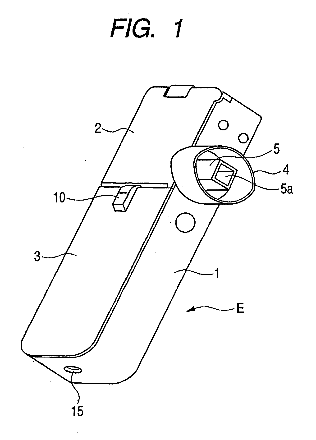
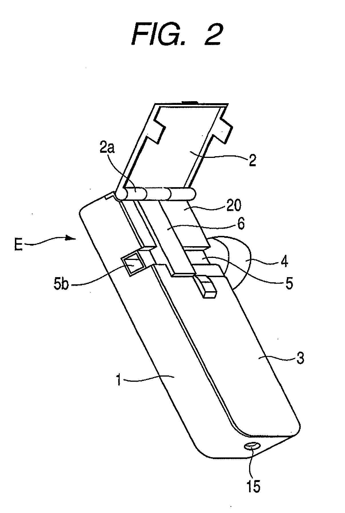
[0042]FIG. 1 is a perspective view showing the appearance of an inhaler according to an embodiment of the medicine ejection device of the present invention. In FIG. 1, reference character 5a denotes an outlet. FIG. 2 is a perspective view showing a state in which an access cover of the inhaler shown in FIG. 1 is opened. In FIG. 2, reference character 2a denotes a hinge and reference character 5b denotes an intake (inlet).

[0043]An inhaler E of this Example includes a box-like housing main body 1, and a front cover 3 and an access cover 2 provided on its openable side.

[0044]The front cover 3 is integrally provided so as to close the openable side of the housing main body 1 at the one-side top in the lengthwise direction. The access cover 2 is swing-movably fitted via a hinge 2a, to the other end of the openable side of the housing main body 1 in the lengthwise direction, and is always pressed by a return spring (not shown) in the opening direction. The front cover 3 is provided with a...

example 2

[0068]An inhalation process according to another embodiment will be described along the flow chart shown in FIG. 6. In this embodiment, all the above parameters are measured and taken into account to decide the ejection operating period.

[0069]First, when a power switch is pushed by a user, the device is brought into the starting mode (S101: START). After the starting mode has been activated, it is checked whether or not the medicine ejection unit 6 is loaded (S102: EJECTION UNIT ON?). If it is not loaded, a warning to inform the user of the fact that the medicine ejection unit 6 is not loaded is displayed (S121: WARNING, REPLACE EJECTION UNIT), and power supply is shut off (S122: POWER OFF), through which the device is stopped (S123: END).

[0070]Where, e.g., the medicine ejection unit 6 effects ejection by an ejection head 8 having an electrothermal conversion element in a thermal jet system, a detecting means of the medicine ejection unit 6 is aimed at measuring the resistance value...


PUM


Abstract

A medicine ejection device is provided allowing a medicine with a desired droplet diameter to be inhaled at a constant rate. The medicine ejection device has a decision part at which the ejection operating conditions of a medicine ejection part for ejecting the medicine are decided in accordance with at least one of an open-air environment or a state of the medicine during use of the device. The device ejects the medicine according to the ejection operating conditions decided by the decision part.

Description

BACKGROUND OF THE INVENTION[0001]1. Field of the Invention[0002]This invention relates to a medicine ejection device such as an inhaler, which ejects medicines to be administered to users.[0003]2. Related Background Art[0004]In medicine inhalers which allow users to inhale and take medicines, treatment for users is being realized in which information databases such as electronic medical records can be utilized. Such medicine inhalers are portable terminals having in combination i) a memory means which stores information concerned with each individual user, inclusive of information on user's medical records and prescription and ii) a medicine ejection device which ejects a medicine to allow users to inhale it. They also have an ejection control means which controls the medicine ejection device in accordance with inspiration profiles of users to eject the medicine so that the users can inhale the medicine in conformity with prescription information.[0005]In the medicine inhalers descr...

Claims


Application Information

Patent Timeline
IPC IPC(8): A61M11/00
CPCA61M11/041A61M15/0085A61M15/02A61M2016/0015A61M2016/0027A61M2202/064A61M16/142A61M2205/50A61M2205/8206A61M11/001A61M11/042A61M15/025A61M2205/3368
Inventor HAMANO, SOJIIMAI, MITSURU
Owner CANON KK
Why Eureka
Eureka Blog
Learn More