Spill Containment Device

a technology of containment device and liquid transfer device, which is applied in the direction of transportation and packaging, functional valve type, liquid transfer device, etc., can solve the problems of most common spillage, contamination of ground water, and other undesirable consequences

Inactive Publication Date: 2008-01-31
S BRAVO SYST
View PDF6 Cites 16 Cited by
  • Summary
  • Abstract
  • Description
  • Claims
  • Application Information

AI Technical Summary

Problems solved by technology

When underground storage tanks adapted to house large amounts of gasoline or other environmental hazardous liquids underneath retail service stations are being filled, the fluids may be spilled and leak into the ground, potentially causing contamination of ground water and leading to other undesirable consequences.
Specifically, spillage most often occurs during connection and disconnection of a fuel hose to a riser pipe leading down to the storage tank.
However, existing spill containment devices have been prone to leakage, thereby defeating the purpose of the device.
Particularly, such spill containment devices often rely on mechanical seals, such as gasket seals and penetration fittings that rely heavily on hose clamps and fasteners, which are more susceptible to leaks than, for example, threaded pipe connections.
However, the bellows are susceptible to physical and chemical stress cracking and may have to be replaced often.

Method used


Image

  • Spill Containment Device
  • Spill Containment Device
  • Spill Containment Device

Examples


Embodiment Construction

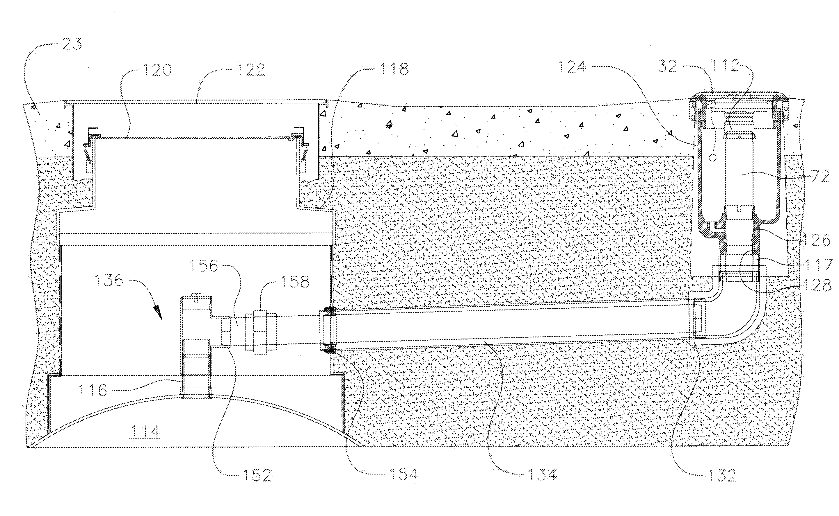
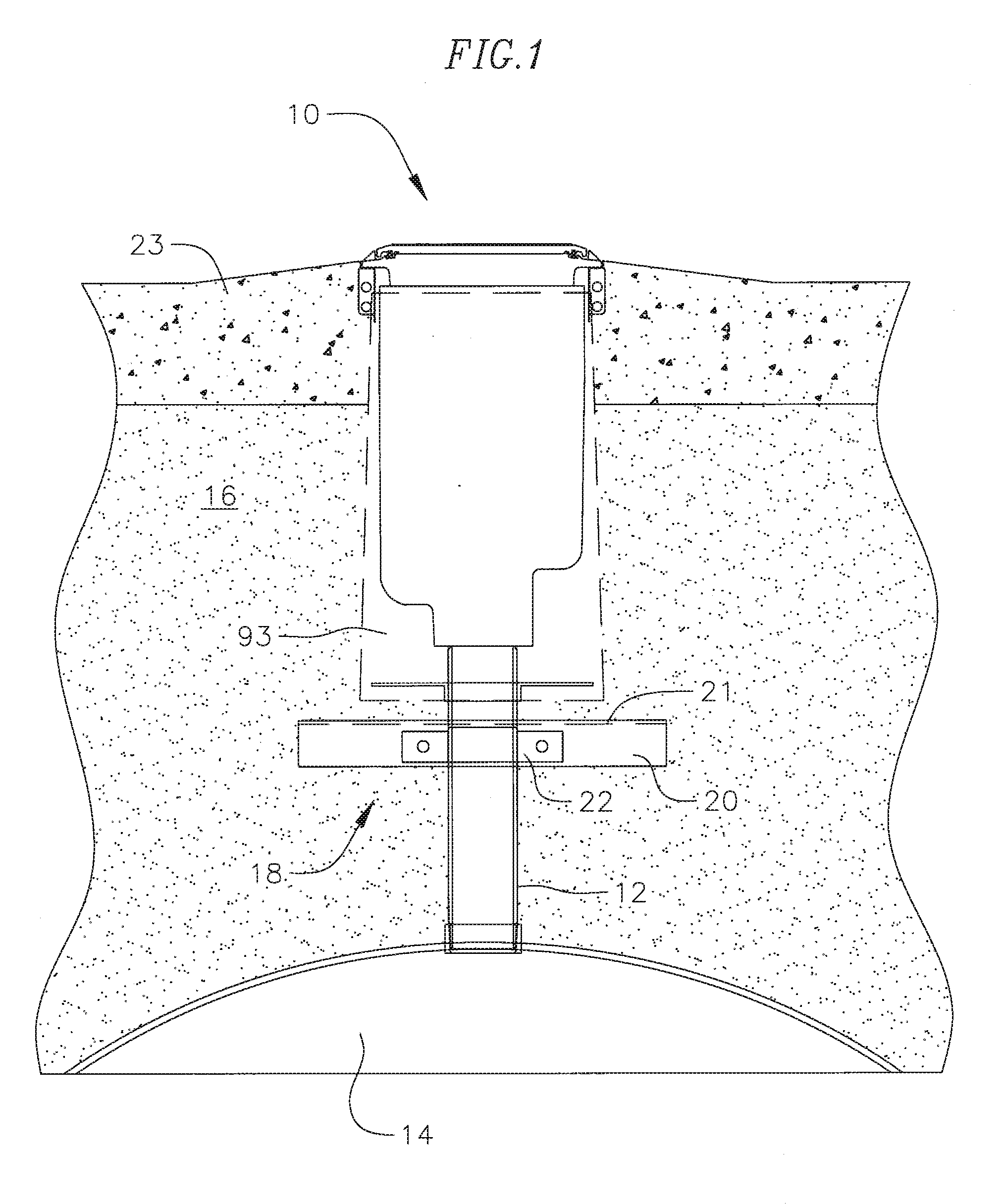
[0019]With reference to FIG. 1, a spill containment device 10 is mounted to a riser pipe 12 extending from a storage tank 14. Generally, the storage tank 14 is disposed in an excavation and covered with soil. A layer of pea gravel 16 may be filled over the soil in the excavation and a concrete apron 23 may be poured over the gravel 16 to define a space. The spill containment device 10 may be disposed into a space provided by the skirt 93 so as to be surrounded by the concrete apron 23 and pea gravel 16 such that an interior of the spill containment device is accessible from above.

[0020]An anti-rotation anchor 18 may be attached to the riser pipe 12 to prevent the unintended rotation of the riser pipe during removal or installation of the spill containment device 10 onto the riser pipe. In one exemplary embodiment, the rotation anchor may comprise a plate 20 attached to the riser pipe 12 by a bracket 22, the plate providing resistance to the torsional forces applied during removal or...


PUM


Abstract

A spill containment device for a fluid storage tank filling system including a threaded riser pipe extending from a storage tank and a drop tube including a flange at one end with a conduit extending from the flange, through the riser pipe and into the storage tank. The spill containment device includes a tubular base having an inwardly protruding shoulder adapted to receive the flange of the drop tube, lower threads below the shoulder adapted to mate with the threaded riser pipe; and upper threads above the shoulder. A receptacle is attached to the tubular base, the receptacle having an open upper end. A threaded compression ring is provided, the threaded compression ring adapted to mate with the upper threads of the tubular base and attach the drop tube to the tubular base.

Description

CROSS-REFERENCE TO RELATED APPLICATION(S)[0001]This application claims priority to and the benefit of U.S. Provisional Application No. 60 / 833,643 filed Jul. 26, 2006, in the U.S. Patent and Trademark Office, the entire content of which is incorporated herein by reference.BACKGROUND OF THE INVENTION[0002]The present invention relates to a spill containment device, and more specifically to a spill containment device for preventing ground contamination by liquid fuels and other hazardous fluids.[0003]When underground storage tanks adapted to house large amounts of gasoline or other environmental hazardous liquids underneath retail service stations are being filled, the fluids may be spilled and leak into the ground, potentially causing contamination of ground water and leading to other undesirable consequences. Specifically, spillage most often occurs during connection and disconnection of a fuel hose to a riser pipe leading down to the storage tank.[0004]Various spill containment devi...

Claims


Application Information

Patent Timeline
Patent Type & Authority Applications(United States)
IPC IPC(8): B67D5/60B67D7/78
CPCB67D7/3209Y10T137/5762
Inventor BRAVO, SERGIO M.MUKAI, DON K.
Owner S BRAVO SYST
Why Eureka
Try Eureka