System and method for dividing a flow of objects

Inactive Publication Date: 2008-01-31
INDAG GES FUER INDBEDARF & BETRIEBS
View PDF7 Cites 13 Cited by
  • Summary
  • Abstract
  • Description
  • Claims
  • Application Information

AI Technical Summary

Benefits of technology

[0005] Preferably, the slides are pivotally mounted on a band that transports the slides in a circular motion so that the slides can return to the start position after displacing an object to the desired location. A guide can be provided to

Problems solved by technology

The high speed can cause undesired deformat

Method used


Image

  • System and method for dividing a flow of objects
  • System and method for dividing a flow of objects
  • System and method for dividing a flow of objects

Examples


Example

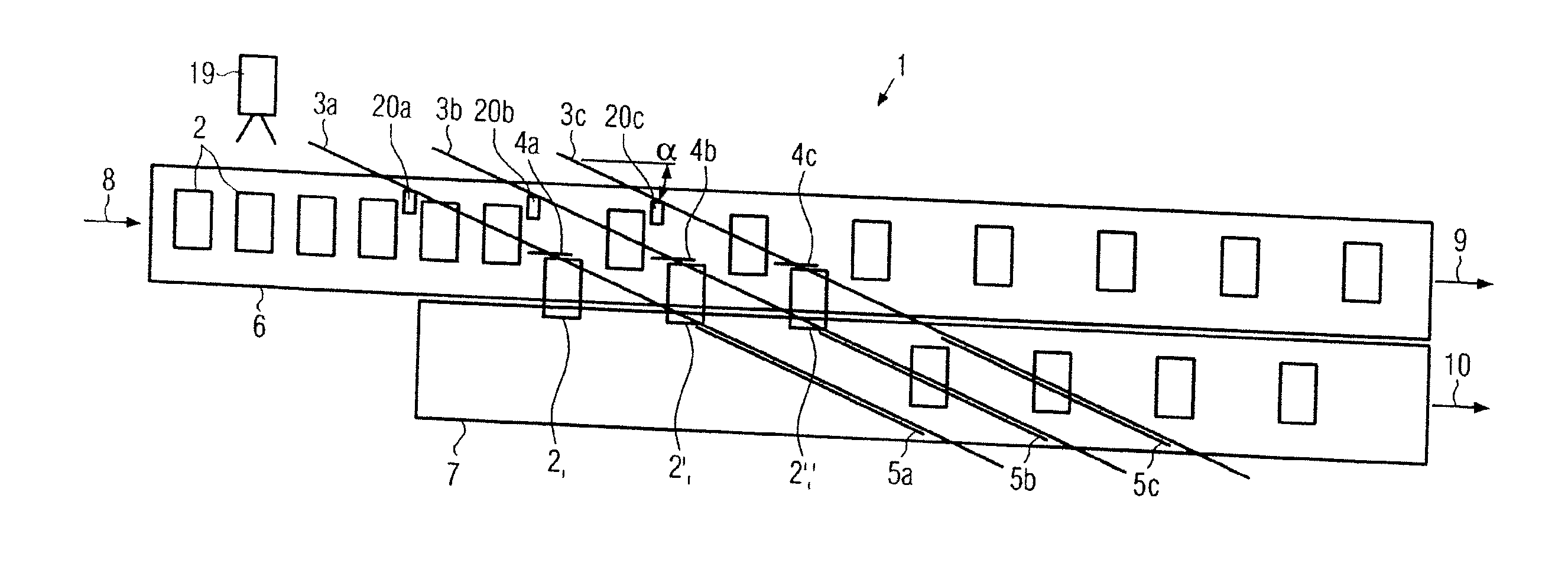
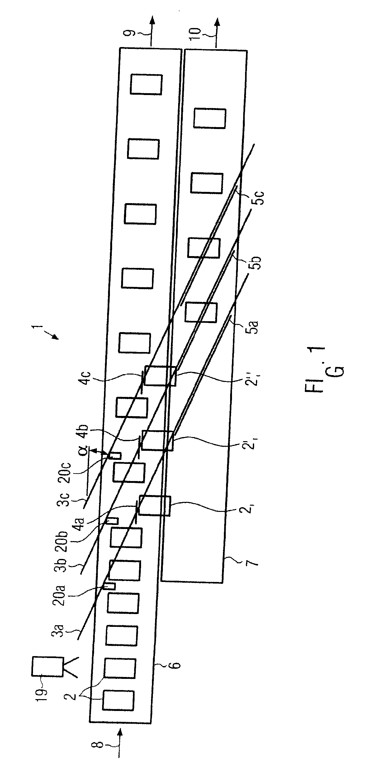
[0015] Reference is made to FIGS. 1-2, wherein a conveyor 6 for transporting objects 2 is illustrated. Whereas objects 2 are illustrated as being conveyed having equivalent spacing between each object, it is to be understood that varying and / or irregular spacing are also contemplated.

[0016] As shown, objects 2 can be transported by the conveyor 6 in direction 8. In the embodiment shown, a second conveyor 7 is also provided to which some of the objects 2 are transferred. It may be preferable for second conveyor 7 to be adjacent to conveyor 6 proximate where the objects are being displaced toward the second conveyor 7. However, it is to be understood that such an arrangement is not necessary and can be altered without deviating from the scope of the invention.

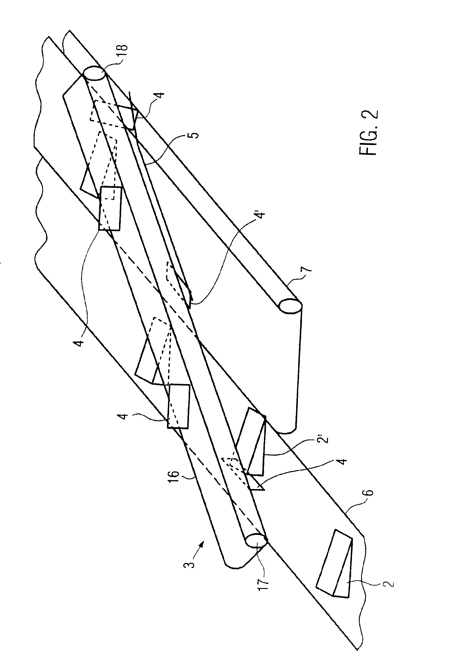
[0017] A dividing system in accordance with an exemplary embodiment of the invention includes slide devices 3a, 3b, 3c which can be constructed and arranged above the conveyors 6, 7. Whereas the example illustrated in FIG. 1 pr...


PUM


Abstract

A system for dividing an object flow can provide slides which are constructed and arranged to displace one or more objects at a time from the object flow toward a different location, preferably another object flow. The slides can be pivotal away from the objects being displaced, thus releasing the objects at the desired location, the slides being reusable as the slides revolve about one or more rollers to and from displacing the objects. Preferably some of the objects are displaced from the object flow at an acute angle with respect to the direction of conveyance, which can provide displacement at a lesser force.

Description

BACKGROUND OF THE INVENTION [0001] This invention relates, in general, to a system, apparatus and method for dividing a flow direction of objects, such as drink containers, into two or more flow directions. For example an object can be displaced from being transported in a first flow direction into a second flow direction. [0002] Most systems currently available for dividing a flow direction of objects include displacing single objects from a flow direction using cams or plungers, which push the single objects from the side of the objects and cause the objects to move out of the first flow direction by displacement into a second flow direction. Flows having high throughput rates or closely spaced objects, however, typically require a high speed at which each single object is pushed out of the flow direction. The high speed can cause undesired deformation in flexible objects, such as foil bags. [0003] In light of the shortcomings described above, it is desirable to provide an apparat...

Claims


Application Information

Patent Timeline
IPC IPC(8): B65G47/10
CPCB65G47/71B65G47/766B65G47/841B65G2201/0238B65G47/22B65G47/52
Inventor WILD, HANS-PETERKRAFT, EBERHARDLECHERT, FRANK
Owner INDAG GES FUER INDBEDARF & BETRIEBS
Why Eureka
Try Eureka