Push-button switch

Inactive Publication Date: 2008-01-31
TSENG WEI HUA
View PDF4 Cites 2 Cited by
  • Summary
  • Abstract
  • Description
  • Claims
  • Application Information

AI Technical Summary

Benefits of technology

[0006]To achieve this object of the present invention, the technical method in present invention is adding a signal-conductor unit in traditional push-button switch. By the way, the signal-conductor can generate a signal when the release-button is pushed and the anticipation delayed-action time circuit can be controlled and turned on or off by detecting the length of signal. In order to provide a better function, the better technical method in

Problems solved by technology

Due to the acceptability in the market, the molds and the cost of manufacture, the standards of the push-button switch can not be changed indiscreetly.
But, the require for mo

Method used


Image

  • Push-button switch
  • Push-button switch
  • Push-button switch

Examples


Example

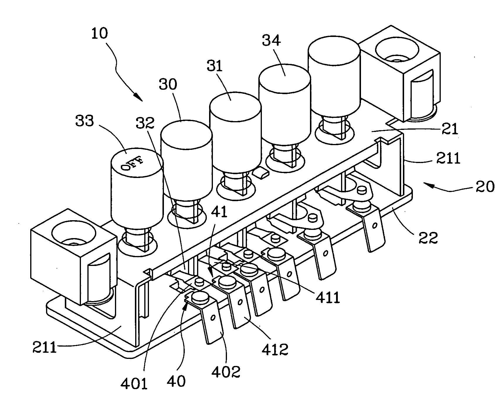
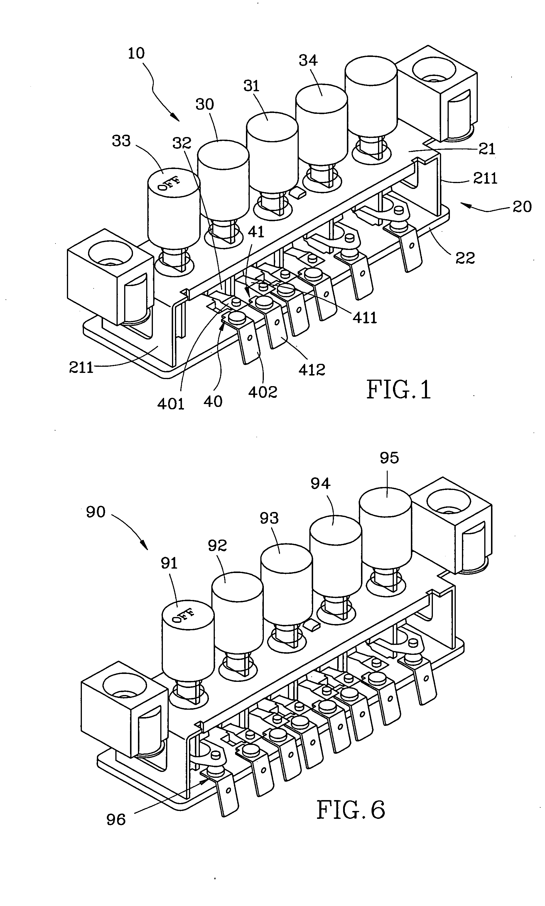
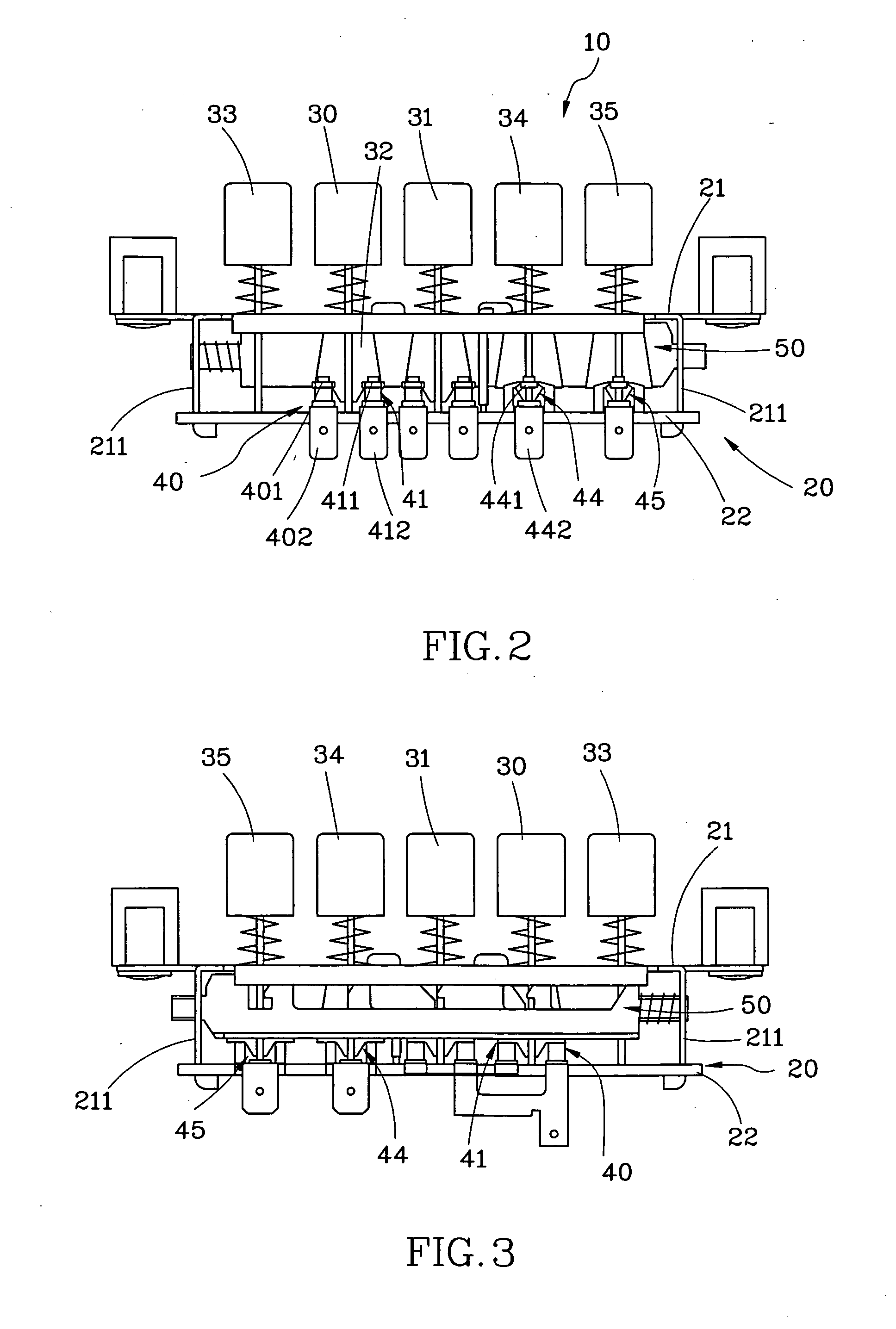
[0013]Referring to FIG. 1 to FIG. 4, a push-button switch 10 of the first embodiment of present invention includes:

[0014]A shell 20 composes of a top plate 21 and a button plate 22. The top plate 21 with two arm portion 211 is made of metal plate by pressing. The button plate 22 is made of insulated material and fixed on the end of two arm portions 211 (this is a prior art structure).

[0015]Two speed-button units 3031 mount on the top plate 21 and each unit has an insulated press-arm 32 at the button end (this is a prior art structure). These two units ( can move up or down by way of push. Each speed-button unit has a couple of conductor sets 4041 at the button and each of the conductor sets includes a conductor 401411 and a connector 402412. This is a broken circuit in normal condition. The press-arm 32 can press the conductors 401411 to move downward and touch the connectors 402412 and make the circuit connected when the corresponding speed-button unit is pushed.

[0016]A lock device...

Example

[0024]Referring to FIG. 6, this is a switch 90 of the second embodiment of present invention. The structures in this embodiment and in the first embodiment are almost the same. There are five buttons therein and the button 91 is a release-button. The button 92 is a high-speed button and the button 93 is a middle-speed button. The button 94 is a low-speed button and the button 95 is a light button. There is no signal-button in the embodiment but a signal-conductor unit 96 mounted under the release-button 91. There are not two speed-buttons but three speed-buttons in the embodiment. The connect method of the wires of this embodiment and the first embodiment are almost the same. This embodiment only changes the high or low speed choices of the motor into high, middle and low speed choices.

[0025]As aforesaid, the push-button switch of present invention can provide more functions to match the desired of custom but not change the traditional scale. Meanwhile, present invention does have t...


PUM


Abstract

A push-button switch includes: a shell composes of a top plate and a button plate. The button plate is made of insulated material. At least two speed-button units mount on the top plate. Each speed-button unit has a couple of conductor set at the button and each conductor set includes a conductor and a connector. The press-arm can press the conductors to move downward and touch the connectors and make the circuit connected when the corresponding speed-button unit is pushed. A lock device mounts in the shell for keeping the button in lock mode position when the button was pushed. A release-button mounts on the top plate and can be pushed to release all buttons from lock mode. A signal-conductor unit that mounts under the signal-button includes a conductor and a connector. The conductor unit forms a signal circuit when the signal-button was pushed.

Description

BACKGROUND OF THE INVENTION[0001]1. Field of the Invention[0002]The present invention relates to a push-button switch and more particularly to a push-button switch that can generate a detective signal to extend the action time of electric equipment.[0003]2. Description of the Related Art[0004]In prior art, push-button switches are well know and popular using on a smoke exhauster, an electric fan and so on. The push-button switches become standard components for a smoke exhauster or an electric fan manufacturer because of the stable structure, the accurate action and also qualify for many safeties verifies. Due to the acceptability in the market, the molds and the cost of manufacture, the standards of the push-button switch can not be changed indiscreetly. But, the require for more functions of electric equipment from the customer are increasing day by day. For example, the customer may hope the smoke exhauster can keep on running for 5 or 10 more minutes after the power turned off t...

Claims


Application Information

Patent Timeline
IPC IPC(8): H01H13/72
CPCF24C7/082H01H13/74H01H13/72H01H13/023
Inventor TSENG, WEI-HUA
Owner TSENG WEI HUA
Why Eureka
Try Eureka