Radial rotary feedthrough and bushing therefor

Inactive Publication Date: 2013-12-24
GAT GES FUR ANTRIEBSTECHN
View PDF18 Cites 2 Cited by
  • Summary
  • Abstract
  • Description
  • Claims
  • Application Information

AI Technical Summary

Benefits of technology

[0025]The measures according to the invention have the effect in particular in relation to high pressures that the sliding sealing surfaces retain their cylindrical shape or, viewed from the inner groove, assume a conically slightly divergent shape, that is to say by virtue of the corresponding pressure effects the sealing gap in the proximity of the groove tends to become somewhat smaller while the sealing gap at the outer ends of the sliding sealing surfaces tends to become somewhat larger. That signifies a conical shape for the sliding sealing surfaces with a very small angle which is of the reversed sign in relation to the cone angle as is known from the state of the art. In other words the (notiona

Problems solved by technology

On the other hand as little fluid as possible should escape between the surfaces sliding against each other, especially when dealing with a corresponding leak is relatively complicated and expensive and difficult.
However, particularly when the fluid is under high pressure, certain deformations of the bush are inevitable, and they can also influence the configuration of the sealing gap between the surfaces of the shaft and the bush, which slide against e

Method used


Image

  • Radial rotary feedthrough and bushing therefor
  • Radial rotary feedthrough and bushing therefor
  • Radial rotary feedthrough and bushing therefor

Examples


Embodiment Construction

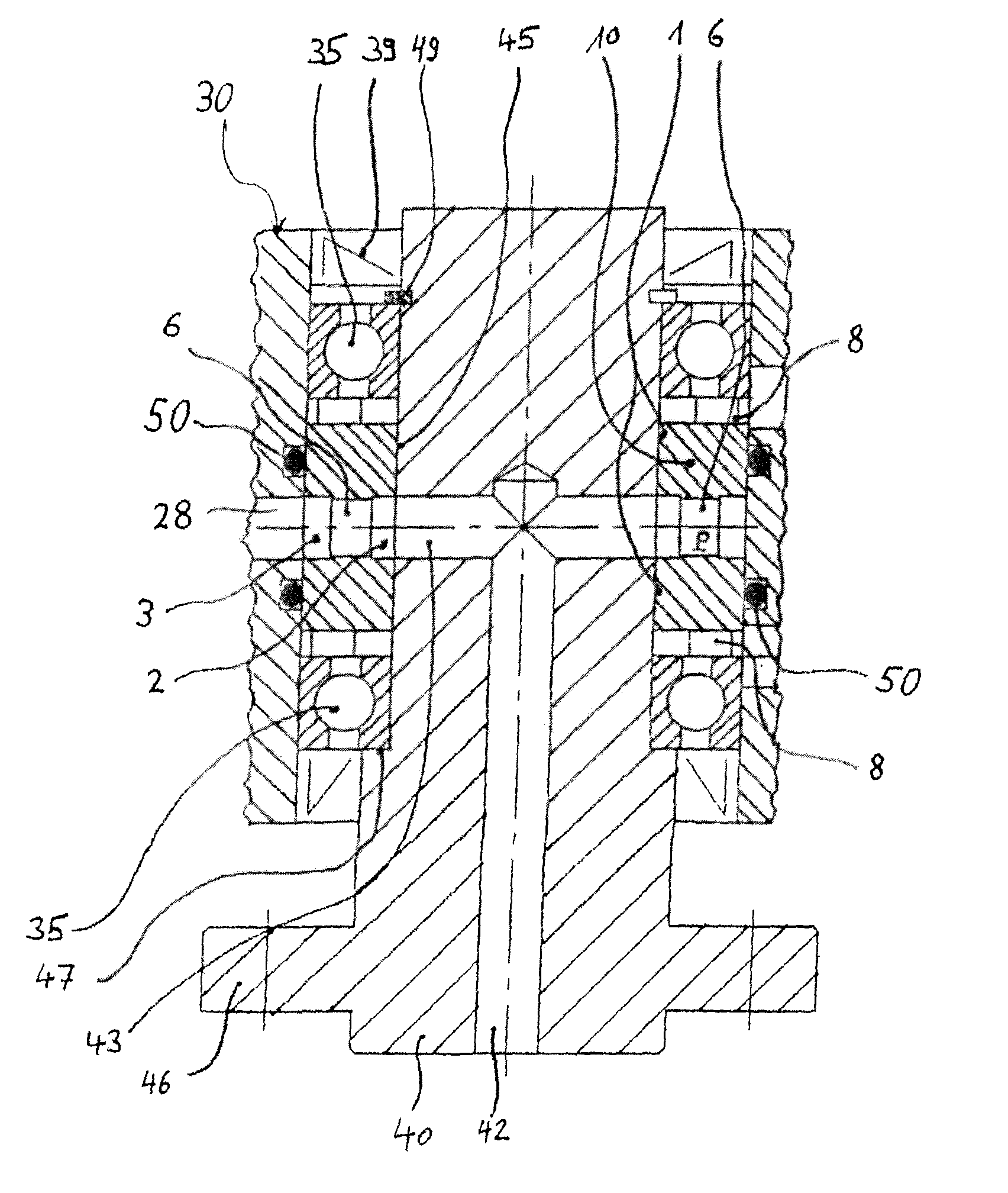
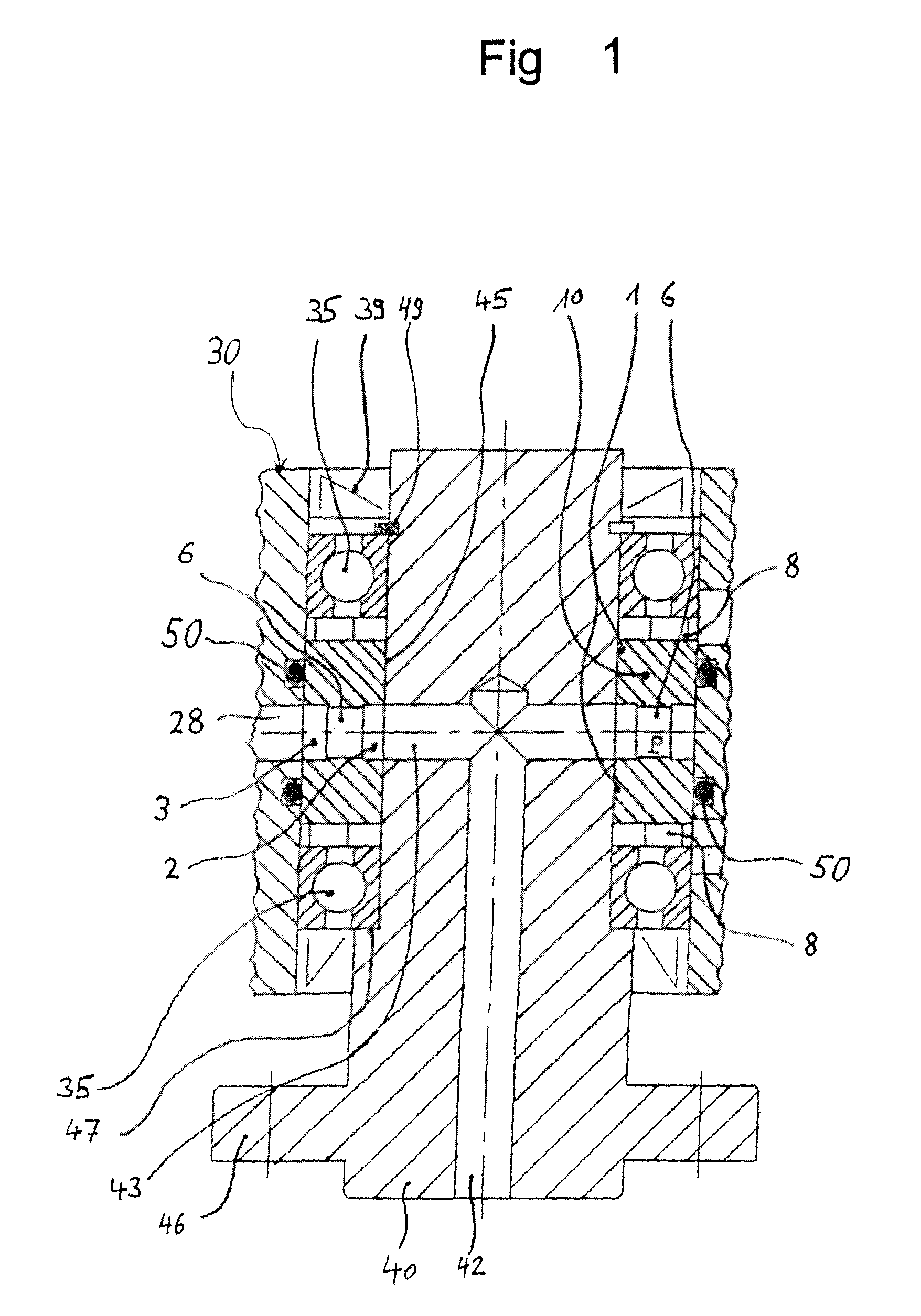
[0037]FIG. 1 shows a generally cylindrical housing 30 which is shown here in broken-away form and in which a bush 10 is accommodated. The axial position of the bush 10 in the interior of the housing 30 is fixed by the position of two ball bearings 35, the position of which is in turn fixed by suitable means such as for example an abutment in the form of a radially projecting step or a circlip (not shown) in the housing and which hold the bush 10 in its position. Disposed in turn within the bush 10 is a rotatable shaft 40 which is connected to the inside races of the ball bearings 35 and has an outer cylindrical sliding sealing surface 45 which is in sealing sliding engagement with the sliding sealing surfaces 1a, 1b of the bush 10.

[0038]A step 47 on the one hand defines with a circlip 49 at the end of the shaft 40 on the other hand the axial position of the shaft 40 in the rotary union joint. Simple termination seals 39 (not acted upon by pressure) are in sliding contact with the sh...


PUM


Abstract

A bush of a radial rotary union joint including a hollow-cylindrical main body whose inner cylindrical surface forms a sliding sealing surface divided by a peripherally extending inner groove into a first and a second sliding sealing surface and having a cylindrical outside surface which is divided by a peripherally extending outer groove into a first and a second outside surface. The wall portion separating the inner and the outer grooves has at least one bore connecting the two grooves. The first and the second outside surface can be sealed off by a stationary sealing ring in relation to a housing embracing the bush. The side surfaces of the inner groove are of the same size within a tolerance threshold of +20% and −35% as the side surfaces of the outer groove. The stationary sealing rings are positioned at an axial spacing from the axially outer end of the oppositely disposed sliding sealing surfaces corresponding to at least 40% and at most 55% of the respective axial length of the sliding sealing surfaces.

Description

CROSS-REFERENCE TO RELATED APPLICATIONS[0001]This application is a §371 National Stage Application of PCT International Application No. PCT / EP2010 / 067327 filed Nov. 11, 2010, which claims priority to German Patent Application No. 10 2009 054 794.0 filed Dec. 16, 2009, both of which are incorporated herein in their entirety.BACKGROUND OF THE INVENTION[0002]The present invention concerns a radial rotary union joint and a bush for same, which forms a radial sliding ring seal. The bush comprises a hollow-cylindrical main body whose inner cylindrical surface forms a sliding sealing surface which is divided by a peripherally extending inner groove into a first and a second sliding seal surface. The bush further has a cylindrical outside surface which is divided by a peripherally extending outer groove into a first and a second outside surface, wherein the wall portion separating the inner and the outer grooves has at least one bore connecting the two grooves and wherein the first and the ...

Claims


Application Information

Patent Timeline
IPC IPC(8): F16L27/00
CPCF16L27/087
Inventor OTT, STEPHANHOFF, DENNIS
Owner GAT GES FUR ANTRIEBSTECHN
Why Eureka
Try Eureka