
Method of permanently joining components formed from metallic materials

a technology of metal materials and components, applied in the field can solve the problems of inability to perform conventional welding techniques, inability to permanently join components, etc., and achieve the effect of reducing the difficulty of permanently joining components, and reducing the number of components

Inactive Publication Date: 2008-01-31
DANA AUTOMOTIVE SYST GRP LLC
View PDF28 Cites 21 Cited by
  • Summary
  • Abstract
  • Description
  • Claims
  • Application Information

AI Technical Summary

Benefits of technology

[0005]This invention relates to a method of permanently joining a first metallic component that is formed from a 5000 series aluminum alloy material and a second metallic component that is formed from a steel alloy material. Initially, one of the first and second components is provided with a layer of an aluminum alloy material that is different from the 5000 series aluminum alloy material used to form the first and second components. For example, the selected one of the first and second components may be provided with a layer of a 6000 series aluminum alloy material. The layer of the 6000 series aluminum alloy material can be provided as a coating on the selected one of the first and seco

Problems solved by technology

As is well known, conventional welding techniques involve the application of heat to localized areas of two metallic members, which results in a coalescence of the two metallic members.
Such conventional welding techniques may or may not be performed with the application of pressure and may or may not include the use of a filler metal.
Although conventional welding techniques have functioned satisfactorily in the past, there are some drawbacks to the use thereof.
However, it has been found to be relatively difficult to securely join a first component that is formed from a 5000 series aluminum alloy material and a second component that is formed from a steel alloy material.

Method used


Image

  • Method of permanently joining components formed from metallic materials
  • Method of permanently joining components formed from metallic materials

Examples


Embodiment Construction

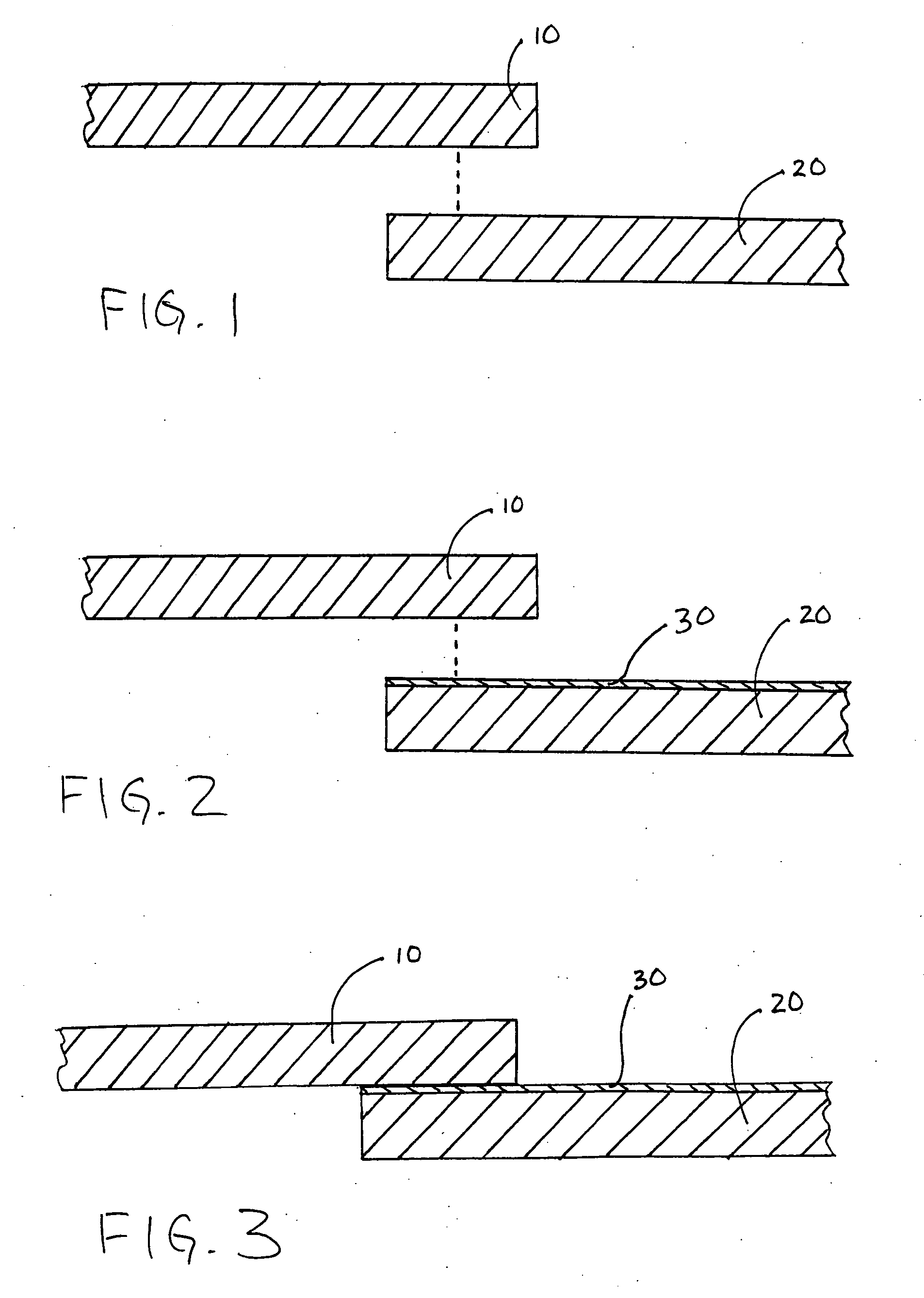
[0012]Referring now to the drawings, there is illustrated in FIG. 1 a first step in the method of this invention, wherein a first metallic component 10 and a second metallic component 20 are provided. As will be explained in greater detail below, the first and second metallic components 10 and 20 are intended to be representative of any metallic structures that are desired to be permanently secured together. The first and second metallic components 10 and 20 can have any desired shapes or combination of shapes including, for example, flat and tubular configurations.

[0013]The first and second metallic components 10 and 20 are formed from different metallic materials. In the illustrated embodiment, the first metallic component 10 is formed from a conventional steel alloy material, and the second metallic component 20 is formed from a 5000 series aluminum alloy material. As is known in the art, 5000 series aluminum alloy material is characterized by a relatively high magnesium content ...


PUM

PropertyMeasurementUnit
Mechanical propertiesaaaaaaaaaa
Metallic bondaaaaaaaaaa

Abstract

A method is provided for permanently joining a first metallic component that is formed from a 5000 series aluminum alloy material and a second metallic component that is formed from a steel alloy material. One of the first and second components is provided with a layer of an aluminum alloy material that is different from the 5000 series aluminum alloy material used to form the first and second metallic components, such as a layer of a 6000 series aluminum alloy material. The layer of the 6000 series aluminum alloy material can be provided as a coating on the selected one of the first and second components or in solid form. After the layer of the 6000 series aluminum alloy material can be provided on the selected one of the first and second components, the first and second components are secured together without the application of heat, such as by magnetic pulse welding, friction welding, and the like.

Description

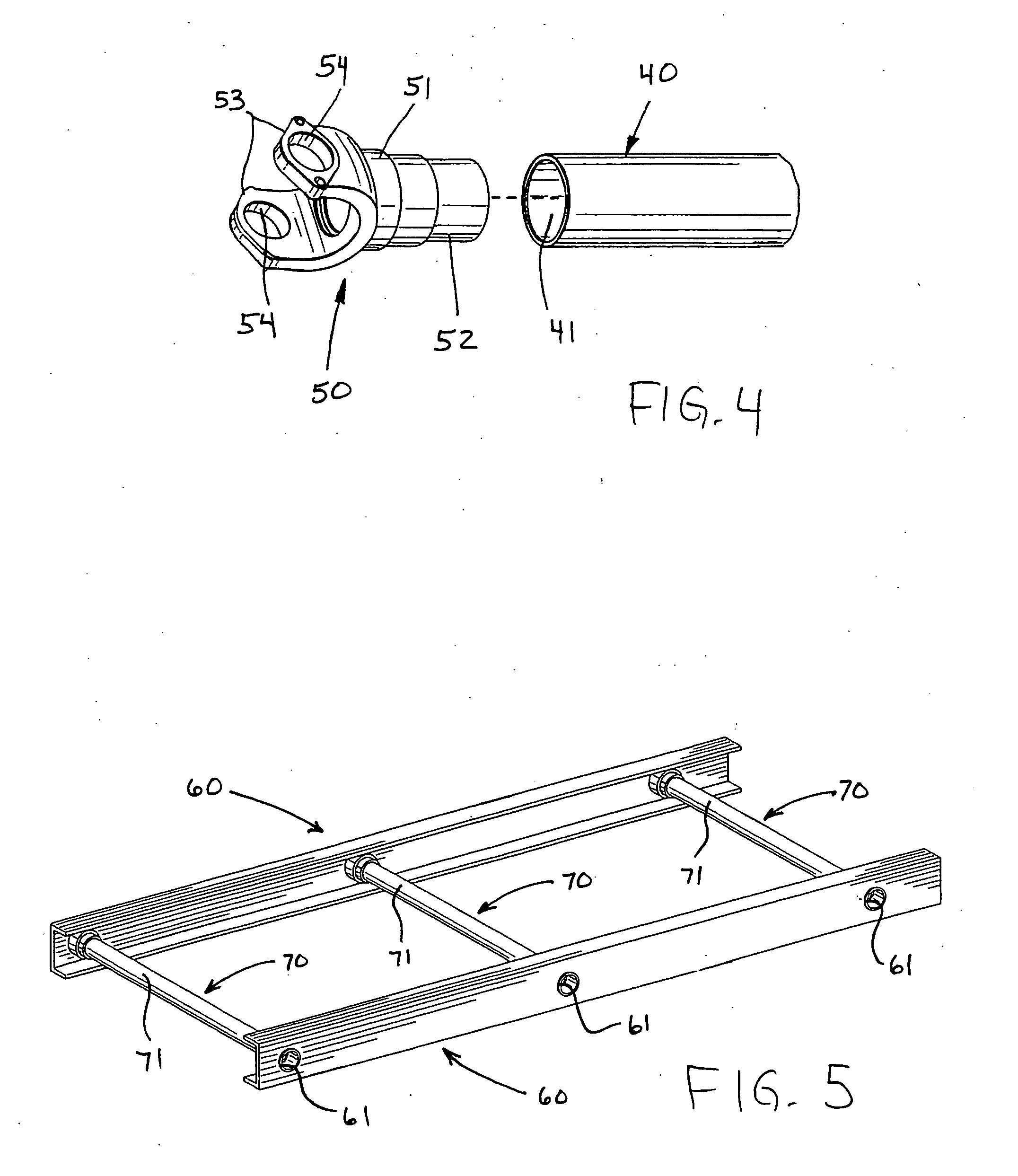
BACKGROUND OF THE INVENTION[0001]This invention relates in general to methods for permanently joining components that are formed from metallic materials. In particular, this invention relates to a method of permanently joining a first metallic component that is formed from a 5000 series aluminum alloy material and a second metallic component that is formed from a steel alloy material.[0002]A wide variety of structures are manufactured by permanently joining first and second metallic components together. For example, in most land vehicles in use today, a drive train system is provided for transmitting rotational power from an output shaft of an engine / transmission assembly to an input shaft of an axle assembly so as to rotatably drive one or more wheels of the vehicle. A typical vehicular drive train system includes a hollow cylindrical driveshaft tube having first and second end fittings (such as tube yokes) that are permanently joined to the opposed ends thereof. Also, many land ve...

Claims


Application Information

Patent Timeline
IPC IPC(8): A47J36/02
CPCB23K20/06B23K2203/20B23K20/129B23K20/12B23K2103/20F16D3/387F16C3/023
Inventor BRENNINGER, GERHARDHORNIG, HANSKATZMAIER, HANS
Owner DANA AUTOMOTIVE SYST GRP LLC
Learn More