Load control device for use with lighting circuits having three-way switches

a technology of load control device and lighting circuit, which is applied in the direction of process control, contact mechanism, instruments, etc., can solve the problems of increasing the cost of components and installation of dimming systems, smart dimmer switches cannot work properly with existing mechanical three-way or four-way switches, and the inability of dimmer switches to provide advanced features of smart dimmer to the end user

Active Publication Date: 2008-01-31
LUTRON TECH CO LLC
View PDF15 Cites 100 Cited by
  • Summary
  • Abstract
  • Description
  • Claims
  • Application Information

AI Technical Summary

Problems solved by technology

Thus, the dimmer switch 152 is not able to provide the advanced set of features of a smart dimmer to the end user.
In the prior art, accessory dimmers are necessary because prior art multi-location dimmers are incompatible with mechanical three-way switches.
Accessory dimmers installed throughout a house can greatly increase the cost of the components and of the installation of a dimming system.
Often, the typical customer is unaware that a remote switch is required when buying a smart dimmer switch for a three-way or four-way system until after the time of purchase when the smart dimmer switch is installed and it is discovered that the smart dimmer switch will not work properly with the existing mechanical three-way or four-way switch.

Method used


Image

  • Load control device for use with lighting circuits having three-way switches
  • Load control device for use with lighting circuits having three-way switches
  • Load control device for use with lighting circuits having three-way switches

Examples


second embodiment

[0089]FIG. 6A shows a simplified block diagram of a three-way lighting control system 600 including a smart three-way dimmer switch 602 according to the present invention. A first detect circuit (or sensing circuit) 636 is coupled across the first triac 510 and a second detect circuit (or sensing circuit) 638 is coupled across the second triac 514. The detect circuits 636, 638 provide control signals to the controller 618 representative of electrical characteristics of the first dimmed hot terminal DH1 and the second dimmed hot terminal DH2, respectively. Each of the electrical characteristics may be a voltage developed across one of the respective triacs. Alternatively, the detect circuits 636, 638 may be placed in series with the dimmed hot terminals DH1, DH2 and the electrical characteristics may be currents through the dimmed hot terminals. In essence, the sensing of the electrical characteristics provides a determination of whether a path of continuity exists between hot and ne...

third embodiment

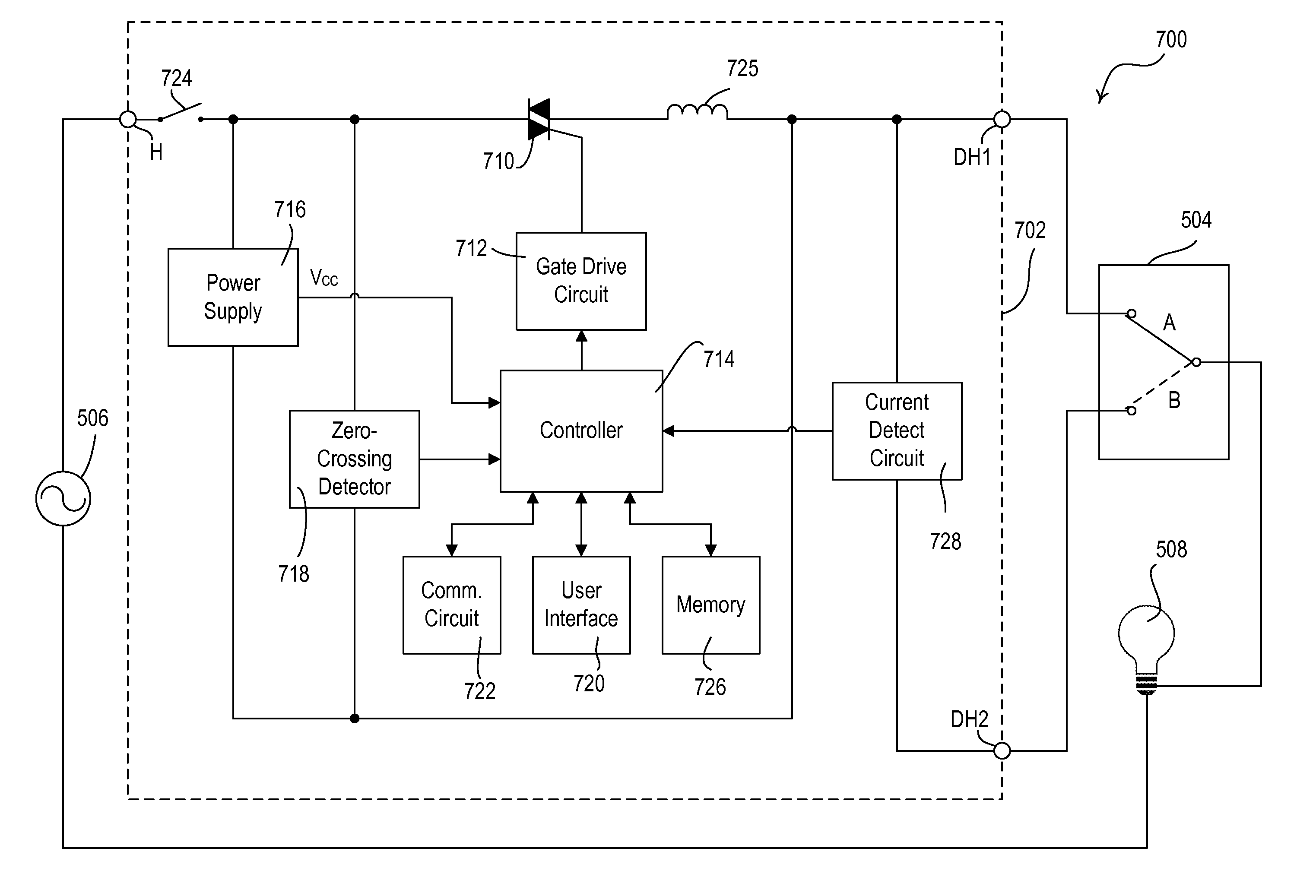
[0096]FIG. 7A shows a simplified block diagram of a three-way lighting control system 700 including a smart three-way dimmer switch 702 according to the present invention. In this embodiment, the dimmer switch 702 includes a single controllably conductive device, for example, a bidirectional semiconductor switch, such as a triac 710. A controller 714 is coupled to the gate of the triac 710 through a gate drive circuit 712 and controls the conduction time of the triac each half-cycle. A power supply 716 is coupled across the triac 710 and generates a DC voltage VCC to power the controller 714. A zero-crossing detector 718 determines the zero-crossing points of the AC voltage source 506 and provides this information to the controller 714. A user interface 720 provides inputs to the controller 714 from a plurality of buttons (including a toggle button) and includes a plurality of LEDs for feedback to a user. A communication circuit 722 allows the controller 714 to transmit and receive ...

fourth embodiment

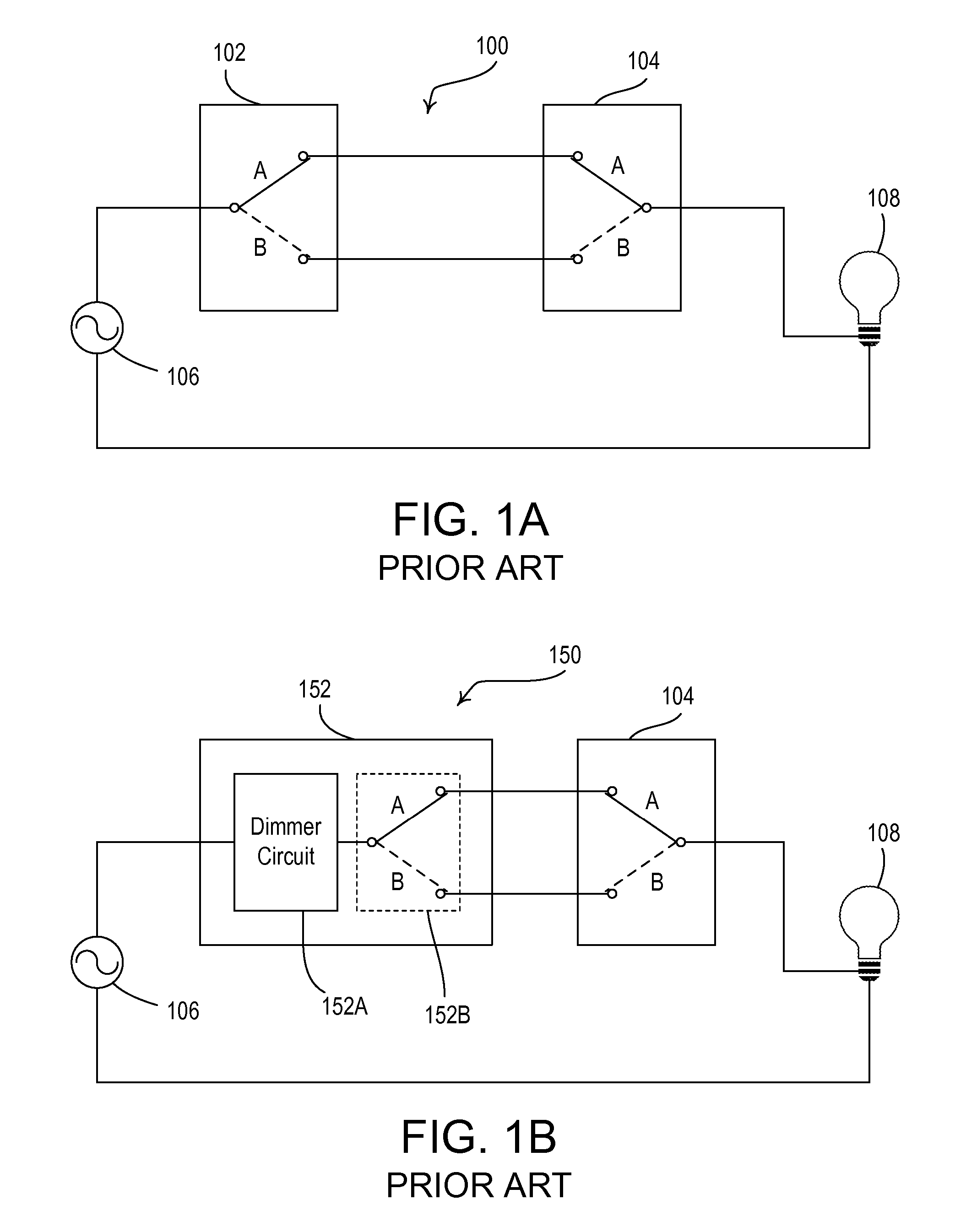
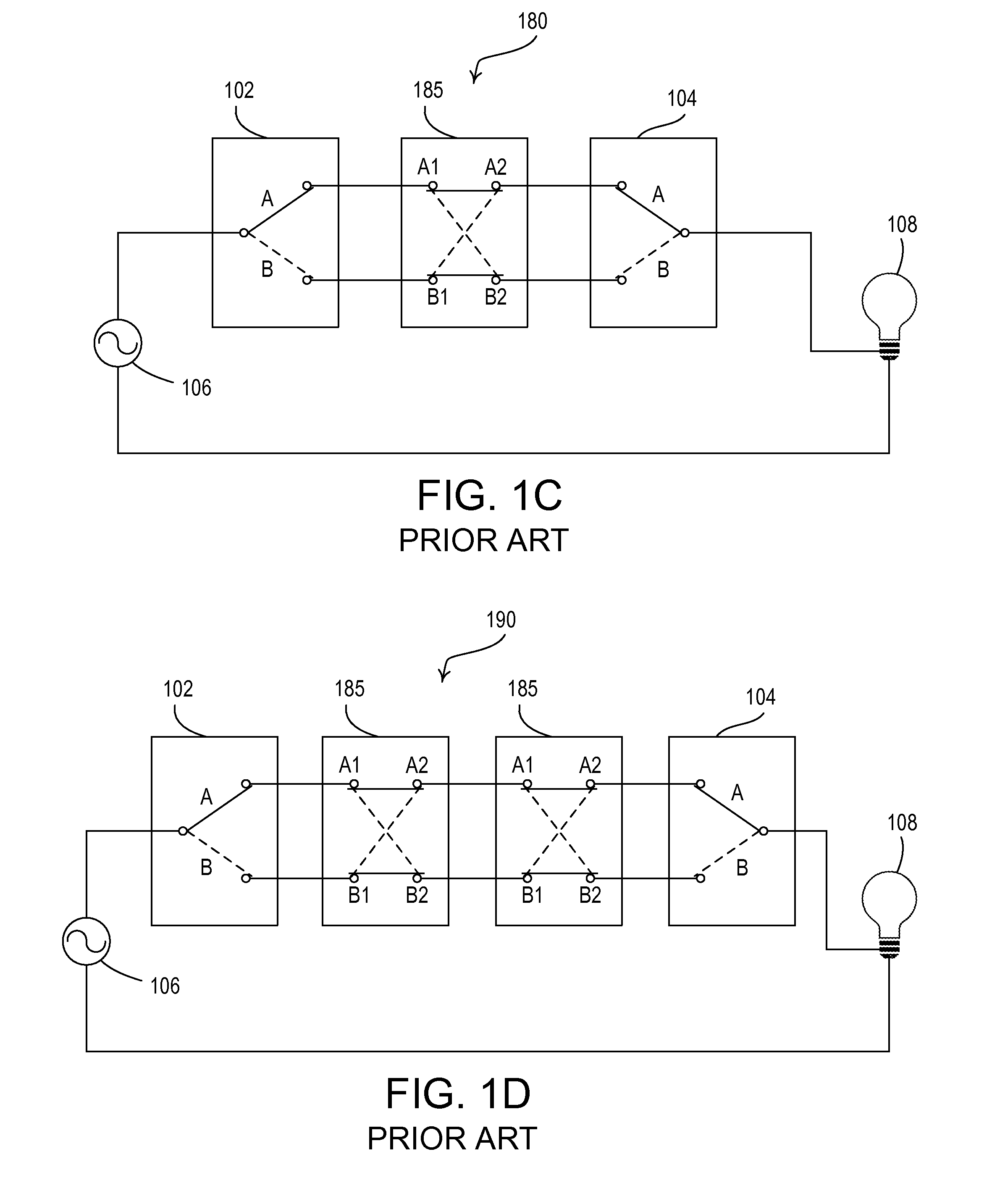
[0101]FIG. 8 is a simplified block diagram of a four-way lighting control system 800 including a smart four-way dimmer switch 802 according to the present invention. The dimmer 802 and two three-way switches 803, 804 are coupled between an AC voltage source 806 and a lighting load 808. The dimmer 802 has replaced the four-way switch 185 in the four-way lighting control system 180 of FIG. 1C.

[0102] The dimmer 802 operates on the same principles as the dimmer 702 of FIG. 7A. However, the dimmer 802 includes an additional hot terminal H2 that is coupled to the three-way switch 803 on the line-side of the system 802. The dimmer 802 further comprises a second current detect circuit (sensing circuit) 829 that is coupled between the hot terminals H, H2 and provides a signal to a controller 814. The second current detect circuit 829 operates in the same manner as the first current detect circuit 728. When current is detected flowing through the second current detect circuit 829, the control...


PUM


Abstract

A smart dimmer for control of a lighting load from an AC power source can replace any switch in a three-way or four-way lighting control system. The smart dimmer can be connected on the line-side or the load-side of a three-way system with a standard three-way switch in the other location. According to one embodiment of the present invention, the dimmer includes two triacs to control the intensity of the connected lighting load. The dimmer preferably includes two gate drive circuits coupled to the gates of the triacs for rendering the triacs conductive each half-cycle of the AC power source. The gate drive circuits include sensing circuits for detect whether the gates currents are flowing after the triacs are rendered conductive. A controller is operable to determine the state of the lighting load in response to whether the gate current is flowing or not flowing.

Description

CROSS-REFERENCE TO RELATED APPLICATIONS [0001] This application is a continuation-in-part of commonly-assigned co-pending U.S. patent application Ser. No. 11 / 767,279, filed Jun. 22, 2007, entitled LOAD CONTROL DEVICE FOR USE WITH LIGHTING CIRCUITS HAVING THREE-WAY SWITCHES, which is a continuation-in-part of commonly-assigned co-pending U.S. patent application Ser. No. 11 / 447,496, filed Jun. 6, 2006, entitled DIMMER SWITCH FOR USE WITH LIGHTING CIRCUITS HAVING THREE-WAY SWITCHES, which claims priority from commonly-assigned U.S. Provisional Application Ser. No. 60 / 687,690, filed Jun. 6, 2005, entitled INTELLIGENT THREE-WAY AND FOUR-WAY DIMMERS. The entire disclosures of all applications are hereby incorporated by reference herein.BACKGROUND OF THE INVENTION [0002] 1. Field of the Invention [0003] The present invention relates to load control devices for electrical wiring systems having three-way switches. In particular, the present invention relates to a dimmer switch that can be su...

Claims


Application Information

Patent Timeline
Patent Type & Authority Applications(United States)
IPC IPC(8): G05F1/00H05B41/36
CPCH05B37/0209Y02B20/48H05B41/3924H05B39/08H05B47/10Y02B20/40H05B47/165
Inventor MOSEBROOK, DONALDROGAN, CHRISTOPHER M.STEFFIE, JAMIE J.BLAKELEY, MATTHEW ROBERT
Owner LUTRON TECH CO LLC
Why Eureka
Try Eureka