Magnetic Element

a technology of magnetic elements and windings, which is applied in the direction of basic electric elements, transformers/inductance details, etc., can solve the problems of insufficient inductance value, difficulty in pulling out the ends of the coil around the winding axis of the drum core, and difficulty in increasing the number of windings of the coil, so as to reduce the leakage of magnetic flux, increase the saturation magnetic flux density, and relax the restriction on the number of windings

Active Publication Date: 2008-01-31
SUMIDA CORP
View PDF17 Cites 20 Cited by
  • Summary
  • Abstract
  • Description
  • Claims
  • Application Information

AI Technical Summary

Benefits of technology

[0045]By configuring the magnetic element as described above, the periphery of the coil is covered with an adhesive coating containing magnetic material, thus enabling leakage magnetic flux to be reduced.
[0046]In another aspect of the present invention, at least one of the center core, the planar core and the side core is formed from compressed metal powder. Configuring the magnetic element as described above enables the saturation magnetic flux density to be increased, thus further enabling the magnetic element to be made more compact.
[0047]With the present invention, a magnetic element the ends of the coil of which can be drawn out from the core easily, is compact, and further, is one in which magnetic saturation does not arise easily, can be obtained. In addition, with the present invention, a magnetic element can be obtained that relaxes restrictions on the number of windings in the coil and thereby enables a large inductance value to be obtained, or, alternatively, relaxes restrictions on the thickness of the winding wire used so as to achieve direct current resistance reduction even if the number of windings is increased. Other features, objects and advantages of the present invention will be apparent from the following description when taken in conjunction with the accompanying drawings, in which like reference characters designate the same or similar parts throughout the figures thereof.

Problems solved by technology

However, in the magnetic elements having the structure described above, there is a problem that the ends of the coil being wound around the winding axis of the drum core are difficult to be pulled out toward the terminals when connecting the terminals with the coil because the ring core surrounds the periphery of the drum core.
As a result, the number of windings of the coils 503 and 504 is limited, and it is impossible to increase inductance value sufficiently.
In addition, as such distance becomes narrower, when an attempt is made to increase the number of windings of the coils 503, 504, it is necessary to reduce the thicknesses of the winding wires, then it becomes impossible to achieve direct current resistance reduction.

Method used


Image

  • Magnetic Element
  • Magnetic Element
  • Magnetic Element

Examples


first embodiment

[0060]First, a description is given of a first embodiment of a magnetic element according to the present invention.

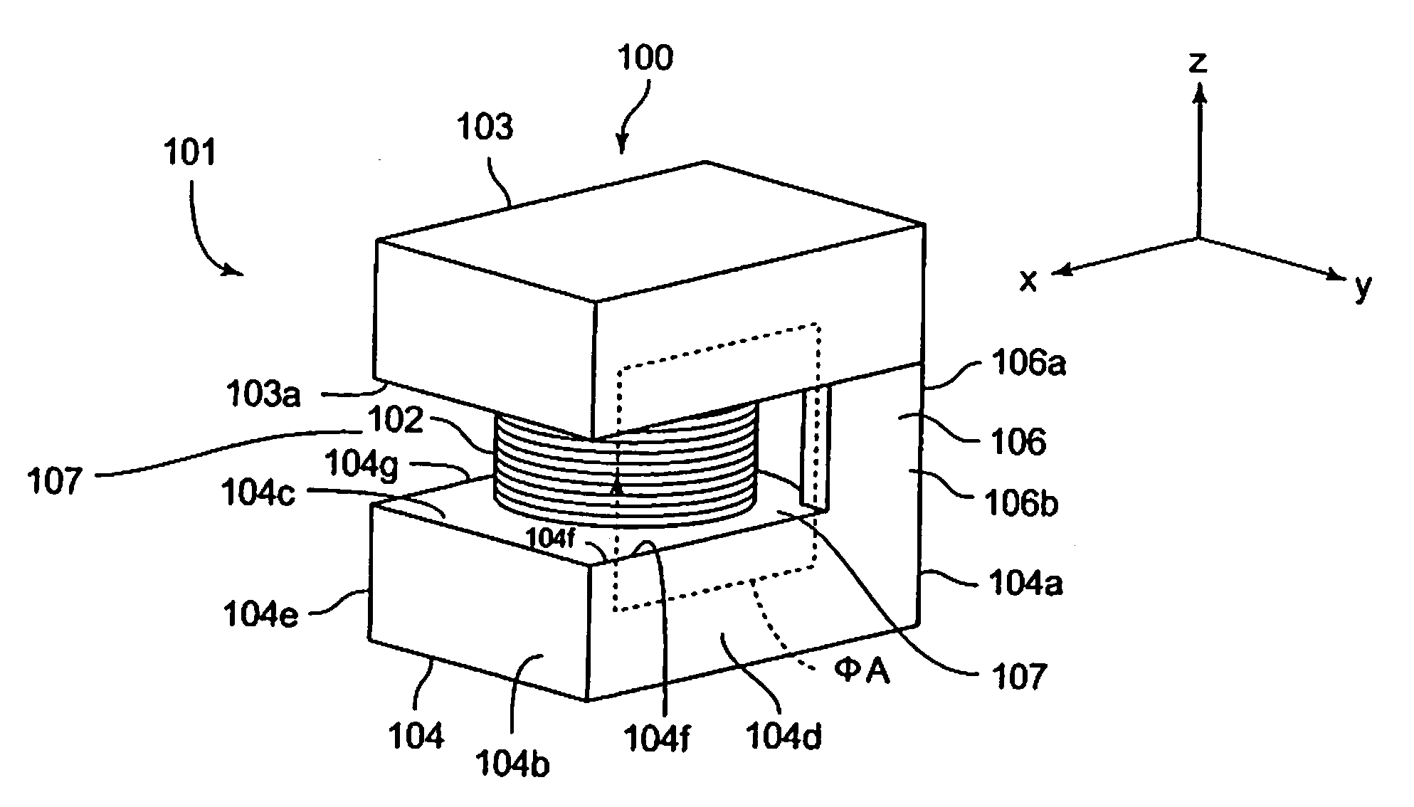
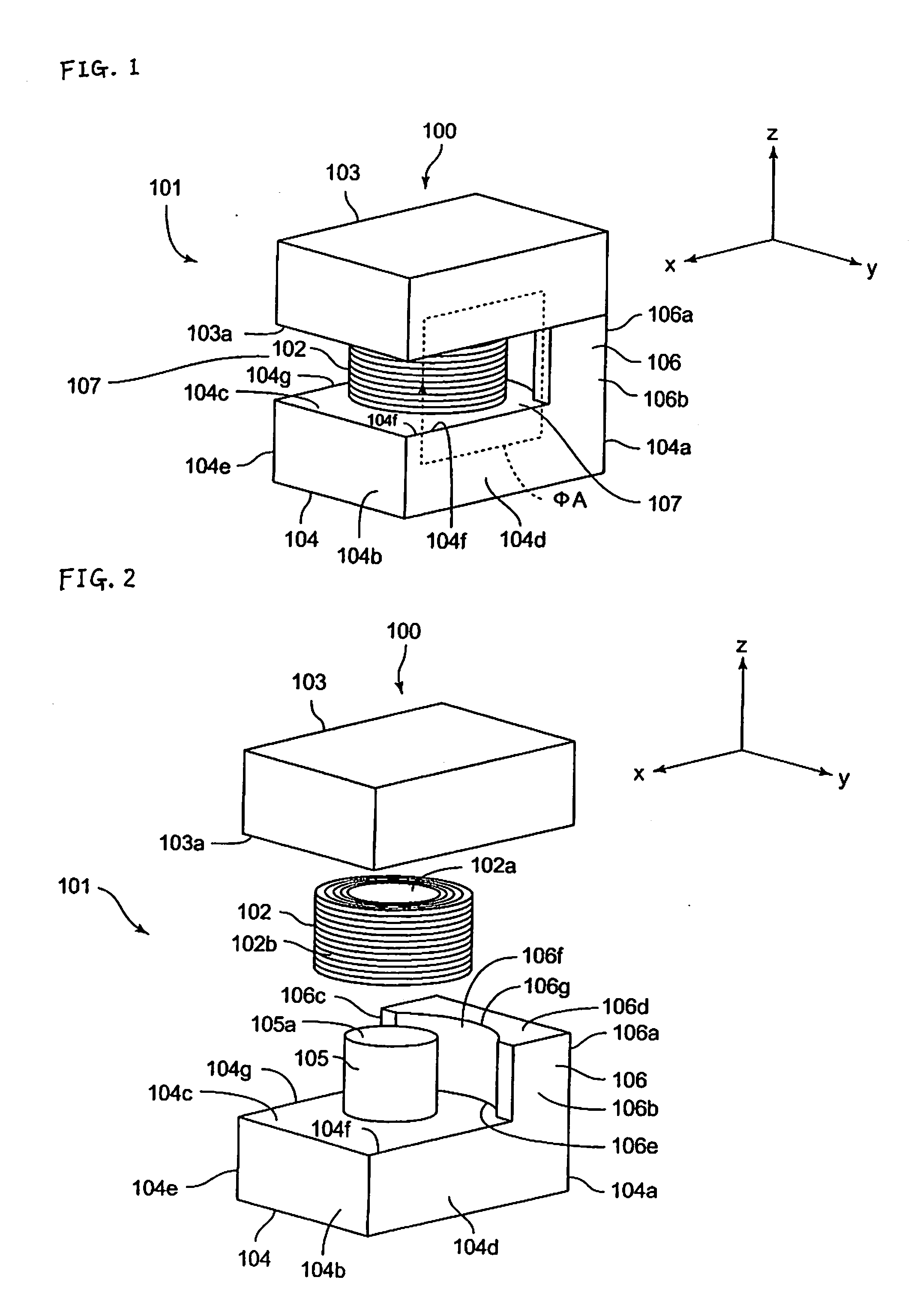
[0061]FIG. 1 is a perspective view of a magnetic element according to the first embodiment of the present invention. In addition, FIG. 2 is an exploded perspective view of the magnetic element shown in FIG. 1.

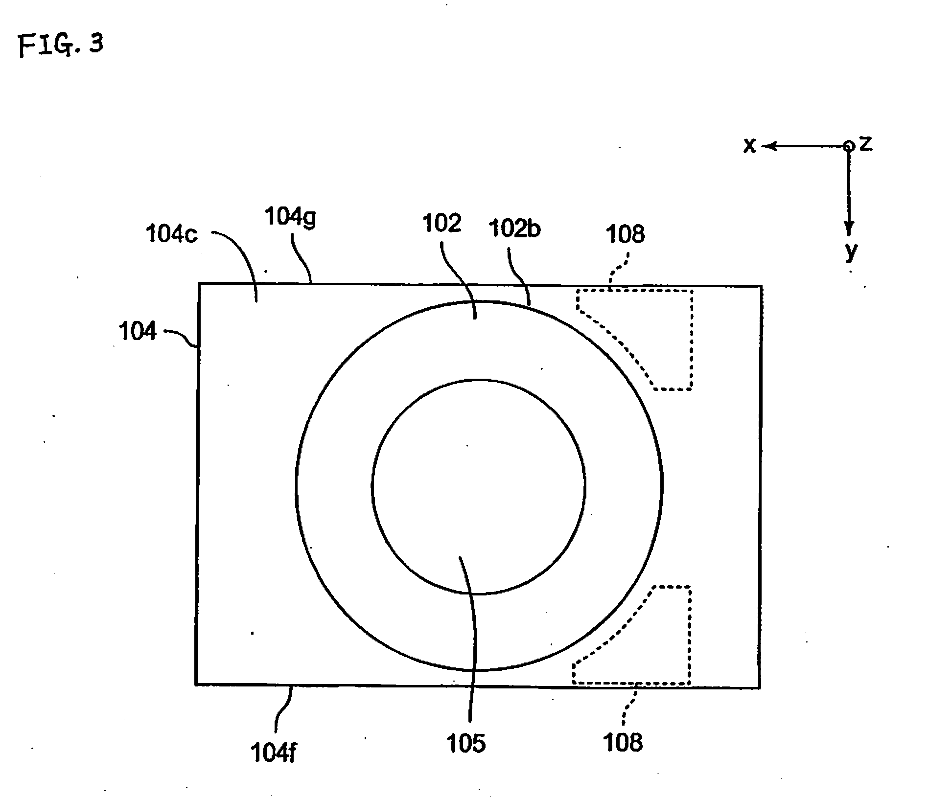
[0062]An inductance element 100 as a magnetic element has a core unit 101 and a coil 102. The core unit 101 has planar cores 103, 104, a center core 105, and a side core 106. The planar cores 103, 104 are wholly thin, flat, rectangular solids in the long direction of the center core 105, and both have substantially identical shapes.

[0063]In the following description, a direction from a short side surface 104a to a short side surface 104b of the planar core 104 is referred to as the front (front side), the reverse direction thereof is referred to as the rear (rear side), a right-hand direction, looking from the rear toward the front, is referred to as right (right s...

second embodiment

[0088]A description is now given of a magnetic element according to a second embodiment of the present invention.

[0089]FIG. 5 is a perspective view of a magnetic element according to a second embodiment of the present invention. In addition, FIG. 6 shows an exploded perspective view of the magnetic element according to the second embodiment of the present invention. In the following description, as with FIG. 1 through FIG. 3, in the drawings the X-axis direction is front (the front side), the Y-axis direction is left (the left side), and the Z-axis direction is up (the top side).

[0090]The inductance element 200 as a magnetic element has a core unit 201 and two coils 202, 203. The core unit 201 has planar cores 204, 205, center cores 206, 207, and a side core 208. The planar cores 204, 205 overall are vertically flattened rectangular bodies, both having substantially the same shape. The center cores 206, 207 are columnar in shape, having their long directions in the vertical directio...

third embodiment

[0115]A description is now given of a magnetic element according to a third embodiment of the present invention.

[0116]FIG. 7 is a perspective view of the magnetic element according to the third embodiment of the present invention. In addition, FIG. 8 is an exploded perspective view of the magnetic element according to the third embodiment of the present invention. In the following description, as with FIG. 1 through FIG. 3, in the drawings the X-axis direction is front (the front side), the Y-axis direction is left (the left side), and the Z-axis direction is up (the top side).

[0117]The inductance element 300 as a magnetic element has a core unit 301 and two coils 302, 303. The core unit 301 has planar cores 304, 305, center cores 306, 307, and side cores 308, 309. The planar cores 304, 305 overall are vertically flattened rectangular bodies, both having substantially the same shape. The center cores 306, 307 are columnar in shape, having their long directions in the vertical direct...


PUM

PropertyMeasurementUnit
heightaaaaaaaaaa
magneticaaaaaaaaaa
areaaaaaaaaaaa

Abstract

To provide a magnetic element the ends of the coil of which can be drawn out from the core easily, is compact, and further, is one in which magnetic saturation does not arise easily. A magnetic element has a core unit provided with a wound coil, a center core 105 inserted into the interior of the inner periphery of the coil, planar cores disposed at both ends of the center core, and a side core disposed between the planar cores and on the outside periphery of the coil. The side core is disposed so as to form an open portion between the two planar cores around the coil, with a recessed portion formed in a surface of the side core facing the coil in which the coil is partially contained.

Description

CROSS-REFERENCE TO RELATED APPLICATIONS[0001]This application relates to and claims priority rights from Japanese Patent Application No. 2006-202926, filed on Jul. 26, 2006, the entire disclosure of which is hereby incorporated by reference herein.BACKGROUND OF THE INVENTION[0002]1. Field of the Invention[0003]The present invention relates to a magnetic element.[0004]2. Background of the Invention[0005]Conventionally, many magnetic elements having a structure in which a rectangular or cylindrical ring core is disposed around the periphery of a circular drum core, in which a coil is wound around a winding axis, are known (see, for example, Japanese patent laid-open publication 2006-73847). However, in the magnetic elements having the structure described above, there is a problem that the ends of the coil being wound around the winding axis of the drum core are difficult to be pulled out toward the terminals when connecting the terminals with the coil because the ring core surrounds t...

Claims


Application Information

Patent Timeline
Patent Type & Authority Applications(United States)
IPC IPC(8): H01F3/00
CPCH01F3/12H01F27/255H01F17/045
Inventor SANO, KAN
Owner SUMIDA CORP
Why Eureka
Try Eureka