
Image-taking apparatus and output image generation method

a technology of image-taking apparatus and output image, which is applied in the field of image-taking apparatus, can solve the problems of subject extension off the photographing region, subject loss, distorted image, etc., and achieve the effect of reducing the change in the dimension of the specific subj

Active Publication Date: 2008-01-31
XACTI CORP
View PDF11 Cites 23 Cited by
  • Summary
  • Abstract
  • Description
  • Claims
  • Application Information

AI Technical Summary

Benefits of technology

[0010]Specifically, for example, the image-taking apparatus may further include a display section for displaying the output image from the image output section. The image output section may execute the change reduction processing to thereby reduce change in a dimension of the specific subject on a display screen of the display section due to change in the distance.
[0016]For example, when a dimension of the specific subject in the photographed image changes due to change in the distance during execution of the change reduction processing, the image output section, based on results of the recognition by the recognition section, may control an angle of view for photographing by the image-taking section after the change to thereby reduce the change in the dimension of the specific subject in the output image due to the change.

Problems solved by technology

Upon performing, with an image-taking apparatus, moving-image photographing on a subject approaching closer from a great distance, there arises a problem that the subject extends off a photographing region unless the zoom factor or the like is adjusted manually during photographing.
In this manual adjustment, the image-taking apparatus moves and thus the photographed image is distorted or the subject is lost in many cases.
These problems are each caused by movement of the subject in relation to the image-taking apparatus.

Method used


Image

  • Image-taking apparatus and output image generation method
  • Image-taking apparatus and output image generation method
  • Image-taking apparatus and output image generation method

Examples


first embodiment

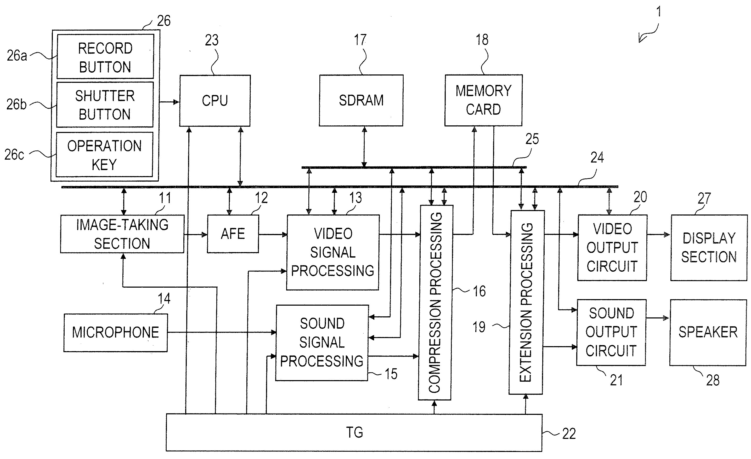
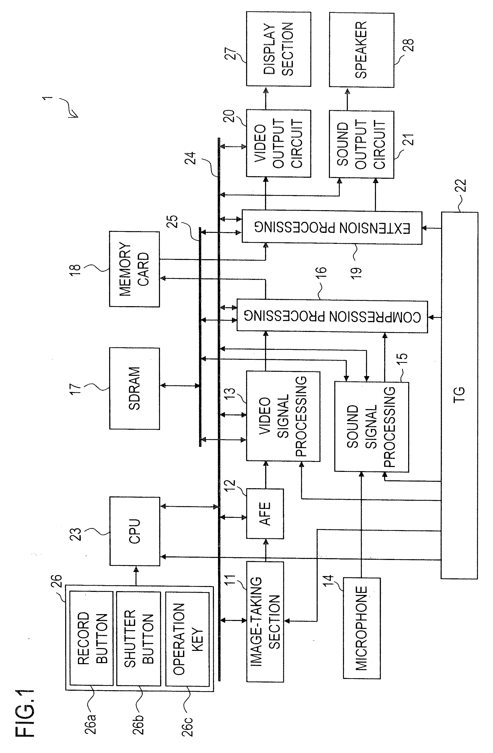
[0062]Next, a characteristic function of the image-taking apparatus 1 will be described.

[0063]This function is called a size adjustment function. First, the first embodiment of the size adjustment function will be described. The size adjustment function is executed in accordance with operation performed on the operation section 26 or the like in the photograph mode.

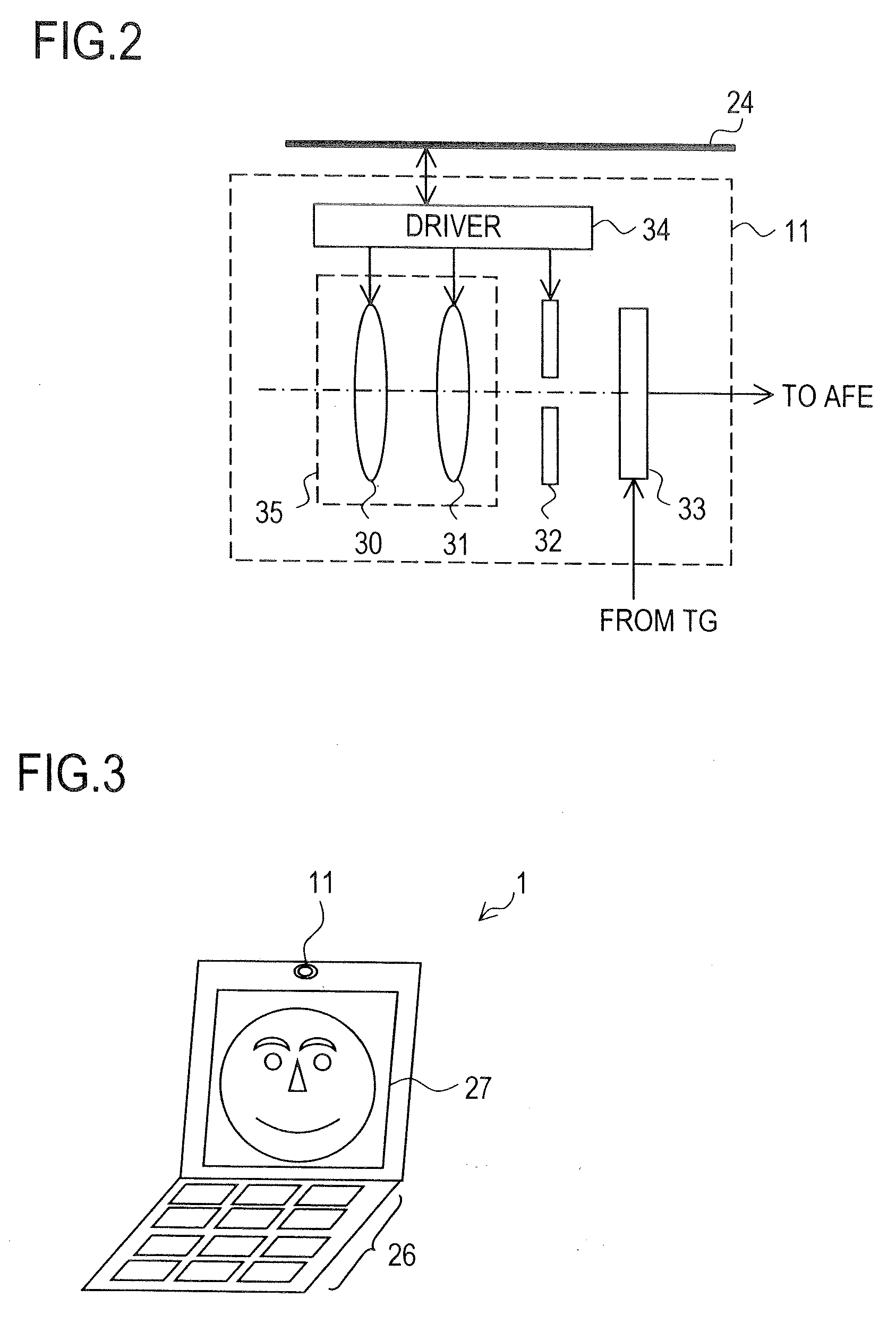
[0064]With the size adjustment function, an entire face or facial parts (eyes, mouth or the like) of a person included in a photographing region are handled as a moving image and they are displayed on the display section 27 on an enlarged scale. At this point, processing such as the one for avoiding a change in the size of a focused specific portion on the display screen is performed as appropriate. The size adjustment function is applied to cases such as where the display section 27 is used as a mirror, and is effective particularly in cases such as where one's face is made up while treating the display section 27 as a m...

first modified processing example

[0120]First, the first modified processing example will be described. In the first modified processing example, based on the state of change in the size (dimension) of the specific portion α in the photographed image or based on the state of change in the size (dimension) of the related portion β in the photographed image, it is judged whether or not processing (change reduction processing) such as one corresponding to steps S301 to S304 of FIG. 11 can be executed. This judgment may be performed based on either of the changes since the size of the specific portion α and the size of the related portion P change in the photographed image in the same manner.

[0121]For simplified description purposes, the first modified processing example will be described below focusing on, of the specific portion α and the related portion β, the specific portion α. To perform the first modified processing example by using the related portion β, for necessary portions only, the specific portion α, the s...

second modified processing example

[0128]Next, the second modified processing example will be described. Also in the second modified processing example, as in the first modified processing example, based on the state of change in the size (dimension) of the specific portion α in the photographed image or based on the state of change in the size (dimension) of the related portion β in the photographed image, it is judged whether or not processing (change reduction processing) such as one corresponding to steps S301 to S304 of FIG. 11 can be executed. In the second modified processing example, the amount of change in the size is referenced.

[0129]For simplified description purposes, the second modified processing example will be described below focusing on, of the both specific portion α and related portion β, the specific portion α. To perform the second modified processing example by using the related portion β, for necessary portions, the specific portion α, the size As, and the reference size AREF can be read as the...


PUM


Abstract

An image-taking apparatus generates an output image from a photographed image obtained by photographing and displays this output image on a display screen of a display section. The image-taking apparatus includes a recognition processing section for recognizing a specific subject (facial region of a person, or a facial component such as eyes) included in the photographed image. Referring to results of this recognition, the image-taking apparatus evaluates the dimension of the specific subject in each photographed image. If the dimension evaluated is relatively large, a relatively small magnification ratio to be employed upon the generation of the output image from the photographed image is provided. If the dimension evaluated is relatively small, a relatively large magnification ratio to be employed upon the generation of the output image from the photographed image is provided. As a result, the dimension of the specific subject in the output image is kept substantially constant.

Description

[0001]This nonprovisional application claims priority under 35 U.S.C. §119(a) on Patent Application No. 2006-207809 filed on Jul. 31, 2006, the entire contents of which are hereby incorporated by reference.BACKGROUND OF THE INVENTION[0002]1. Field of the Invention[0003]The present invention relates to an image-taking apparatus, such as a digital video camera or the like, and also to an output image generation method for use in such an image-taking apparatus.[0004]2. Description of Related Art[0005]It is commonly practiced to make up one's face while holding a mirror in the hand on a vehicle such as a train. Performing such make-up requires carrying the mirror around. In a case where an image-taking apparatus such as a digital video camera is owned, the photographer herself can be photographed with this image-taking apparatus and the image photographed can be checked on the display screen, thereby permitting use of the digital video camera as a mirror.[0006]However, when the photogra...

Claims


Application Information

Patent Timeline
IPC IPC(8): H04N5/228H04N5/222
CPCH04N5/23219H04N5/23248H04N5/23296H04N5/23293H04N5/23254H04N23/611H04N23/68H04N23/6811H04N23/69
Inventor YOSHIDA, HIROAKIMORI, YUKIOHAMAMOTO, YASUHACHIOKADA, SEIJITAKEUCHI, SATORUYOKOHATA, MASAHIRO
Owner XACTI CORP
Learn More