Transmission output control apparatus, multicarrier transmission system, transmission output control method and transmission output control program in computer-readable storage medium

Inactive Publication Date: 2008-01-31
NEC CORP
8 Cites 8 Cited by

AI-Extracted Technical Summary

Problems solved by technology

Moreover, in the environmental conditions of a long transmission distance of the communication line and a lot of noi...

Benefits of technology

[0043]A transmission output control method according to an exemplary aspect of the present invention is for a transmission output control apparatus for controlling a transmission output of a signal to be outputted to a communication line, comprising:
[0044]a transmission output control step for controlling the transmission output of the signal to be outputted to the above described communication line, based on a difference between a transmission distance of the above described communication line and a transmission distance of an adjacent line adjacent to the above described communication line.
[0045]A transmission output control method according to an exemplary aspect of the present invention is for a multicarrier transmission system configured so that a first communication device and a second communication device are connected via a communication line, comprising:
[0046]a transmission output control step for controlling a transmission output o...

Abstract

It is an object of the present invention to provide a multicarrier transmission system for enabling degradation of a transmission speed in an adjacent line adjacent to a communication line, to be avoided. For this purpose, a multicarrier transmission system in the present invention is a multicarrier transmission system configured so that a first communication device and a second communication device are connected via a communication line, wherein the first communication device controls a transmission output of a signal to be outputted to the above described communication line, based on a difference between a transmission distance of the above described communication line and a transmission distance of an adjacent line adjacent to the above described communication line.

Application Domain

Interconnection arrangementsSubstations coupling interface circuits +13

Technology Topic

Embedded systemCarrier signal +5

Image

  • Transmission output control apparatus, multicarrier transmission system, transmission output control method and transmission output control program in computer-readable storage medium
  • Transmission output control apparatus, multicarrier transmission system, transmission output control method and transmission output control program in computer-readable storage medium
  • Transmission output control apparatus, multicarrier transmission system, transmission output control method and transmission output control program in computer-readable storage medium

Examples

  • Experimental program(2)

Example

SECOND EXAMPLE
[0133]Next, a second example will be described.
[0134]In the multicarrier transmission system in the first example, as shown in FIG. 5, the transmission distance of the communication line (300) is previously measured at the xTU-R (200) side (step S1), and the above described measured transmission distance of the communication line (300) is transmitted to the xTU-C (100) side (step S2).
[0135]In a multicarrier transmission system in the second example, as shown in FIG. 10, if the xTU-C (100) determines that the noise equal to or more than the predetermined threshold has occurred on the adjacent line (400) (step A2/Yes), the xTU-C (100) transmits a request for measuring the communication line (300) to the xTU-R (200) side (step A4). Then, the xTU-R (200) is characterized in that if the xTU-R (200) receives the request for measuring the communication line (300) from the xTU-C (100), the xTU-R (200) measures the transmission distance of the communication line (300) (step A5) and transmits the above described measured transmission distance of the communication line (300) to the xTU-C (100) (step A6).
[0136]Thereby, if the xTU-C (100) determines that the noise equal to or more than the predetermined threshold has occurred on the adjacent line (400) (step A2/Yes), the xTU-C (100) can obtain the transmission distance of the communication line (300).
[0137]It should be noted that an obtaining time at which the xTU-C (100) obtains the transmission distance of the communication line (300) is not limited to the time when the xTU-C (100) has determined that the noise equal to or more than the predetermined threshold has occurred on the adjacent line (400), as shown in FIG. 10 described above, and the system can be constructed so that the xTU-C (100) may obtain the transmission distance of the communication line (300) at any time if the transmission distance of the communication line (300) has been obtained when the transmission output value for transmitting within the range of the used frequency band of the adjacent line (400) is calculated at step A8.

Example

THIRD EXAMPLE
[0138]Next, a third example will be described.
[0139]In the multicarrier transmission system in the first and second examples, the transmission distance of the communication line (300) is measured at the xTU-R (200) side, the above described measured transmission distance of the communication line (300) is transmitted to the xTU-C (100) side, and the xTU-C (100) obtains the transmission distance of the communication line (300).
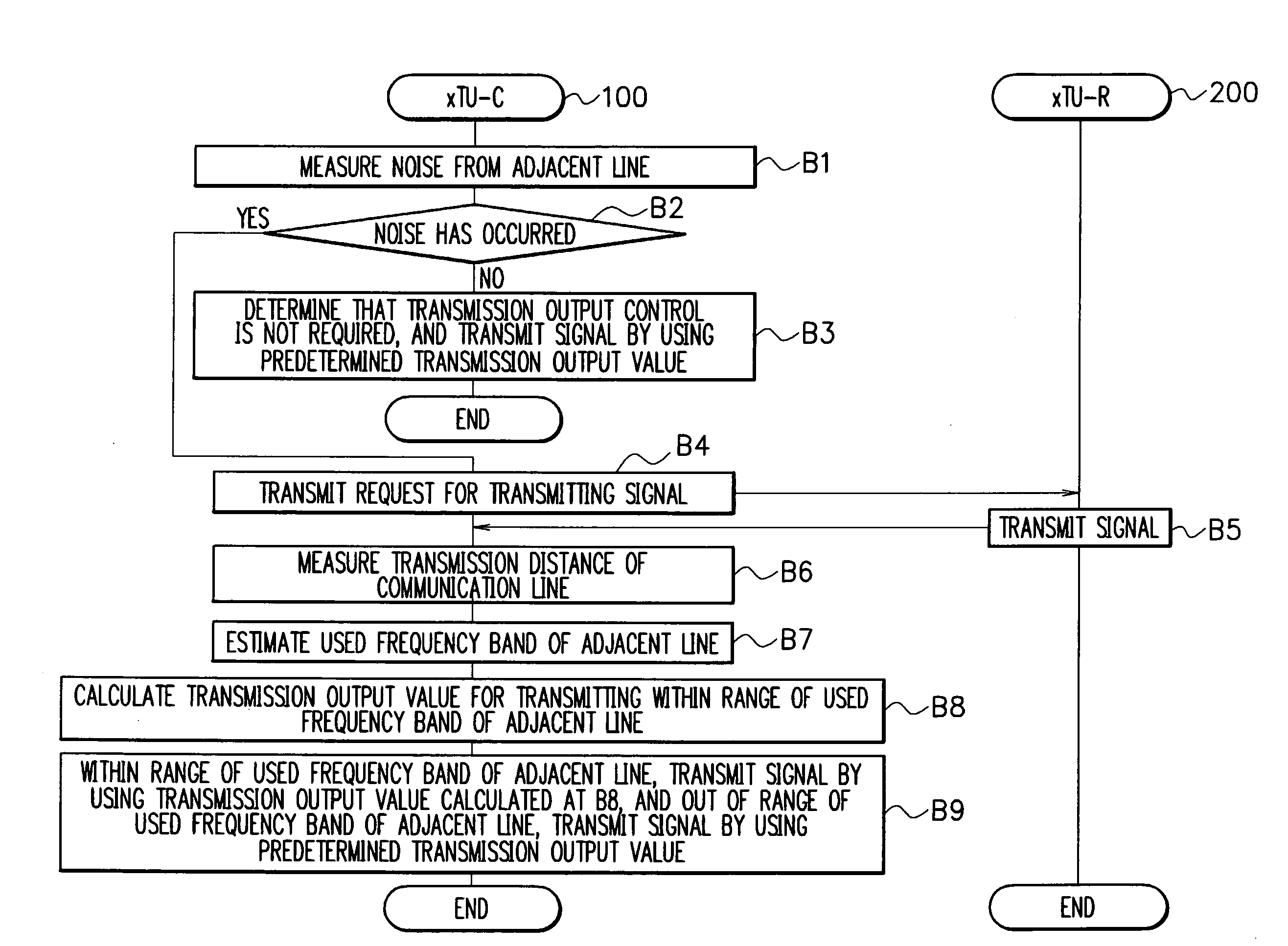
[0140]As shown in FIG. 11, a multicarrier transmission system in the third example is characterized in that the transmission distance of the communication line (300) is measured at the xTU-C (100) side (step B6), and the xTU-C (100) obtains the transmission distance of the communication line (300).
[0141]Thereby, since this example omits the measurement of the transmission distance of the communication line (300) at the xTU-R (200) side, a process at the xTU-R (200) side can be simplified.
[0142]Hereinafter, with reference to FIG. 11, a series of processing operations in the multicarrier transmission system in the third example will be described.
[0143]First, the xTU-C (100) measures the crosstalk noise from the xDSL on the adjacent line (400) by using the spectrum analyzer and the like (step B1).
[0144]Next, the xTU-C (100) determines whether or not the noise equal to or more than the predetermined threshold has occurred on the adjacent line (400), based on the crosstalk noise from the xDSL on the adjacent line (400) measured at step B1 (step B2).
[0145]If the xTU-C (100) determines that the noise equal to or more than the predetermined threshold has not occurred on the adjacent line (400) (step B2/No), the xTU-C (100) determines that the transmission output control is not required, and transmits the signal with the default predetermined transmission output value (step B3).
[0146]Moreover, if the xTU-C (100) determines that the noise equal to or more than the predetermined threshold has occurred on the adjacent line (400) (step B2/Yes), since the signal to be transmitted from the xTU-C (100) to the communication line (300) will affect the signal on the adjacent line (400), the xTU-C (100) performs the transmission output control with respect to the signal to be transmitted to the communication line (300).
[0147]Consequently, the xTU-C (100) transmits a request for transmitting the signal, via the communication line (300) to the xTU-R (200) side (step B4).
[0148]If the xTU-R (200) receives the request for transmitting the signal, the xTU-R (200) transmits the signal via the communication line (300) to the xTU-C (100) side (step B5).
[0149]The xTU-C (100) measures the transmission distance of the communication line (300), based on the receiving level of the signal received from the xTU-R (200) side via the communication line (300), and records the above described measured transmission distance of the communication line (300) (step B6).
[0150]Thereby, the xTU-C (100) can comprehend the transmission distance of the communication line (300).
[0151]Next, the xTU-C (100) estimates the used frequency band which is used by the xDSL on the adjacent line (400), based on the crosstalk noise from the xDSL on the adjacent line (400) measured at step B1 (step B7).
[0152]Moreover, the xTU-C (100) calculates the transmission output value of the signal to be transmitted from the xTU-C (100) to the communication line (300) within the range of the used frequency band estimated at step B7 (step B8).
[0153]Next, the xTU-C (100) performs the transmission output control based on the used frequency band of the xDSL on the adjacent line (400), which has been estimated at step B7, and the transmission output value calculated at step B8 (step B9).
[0154]In this case, within the range of the used frequency band of the xDSL on the adjacent line (400), the xTU-C (100) transmits the signal to the communication line (300) based on the transmission output value: PSD calculated by the above described Formula (2).
[0155]Moreover, out of the range of the used frequency band of the xDSL on the adjacent line (400), the xTU-C (100) transmits the signal to the communication line (300) based on the predetermined transmission output value: PSD(f).
[0156]In this way, the xTU-C (100) in this example calculates the transmission output value which has a less effect on the adjacent line (400), based on the difference between the transmission distance of the communication line (300) used by the xTU-C (100) and the transmission distance of the adjacent line (400) adjacent to the communication line (300), and controls to transmit the signal to the communication line (300) by using the above described calculated transmission output value.
[0157]Thereby, the xTU-C (100) can measure the transmission distance of the communication line (300) at the xTU-C (100) side, use the above described measured transmission distance of the communication line (300) and the transmission distance of the adjacent line (400) which has been previously obtained by the xTU-C (100) to suppress the transmission output value of the signal to be transmitted to the communication line (300), and control so that it may not affect the transmission speed of another xDSL which is using the adjacent line (400).
[0158]Consequently, the xTU-C (100) can suppress the crosstalk of the xDSL installed in the RT, and avoid the degradation of the transmission speed of the adjacent xDSL installed in the center.
[0159]It should be noted that an measuring time at which the xTU-C (100) measures the transmission distance of the communication line (300) is not limited to the time when the xTU-C (100) has determined that the noise equal to or more than the predetermined threshold has occurred on the adjacent line (400), as shown in FIG. 11 described above, and the system can be constructed so that the xTU-C (100) may measure the transmission distance of the communication line (300) at any time if the transmission distance of the communication line (300) has been measured when the transmission output value for transmitting within the range of the used frequency band of the adjacent line (400) is calculated at step B8.
[0160]It should be noted that the above described examples are preferred examples of the present invention and the scope of the present invention is not limited only to the above described examples. Those skilled in the art can modify or substitute the above described examples within a range without departing from the gist of the present invention to construct a form to which various alterations have been applied.
[0161]For example, in the multicarrier transmission system in the above described examples, if the xTU-C (100) measures the crosstalk noise from the xDSL on the adjacent line (400), the system can be constructed so that the xTU-C (100) may measure the noise of the far end crosstalk from the adjacent line (400) or measure the noise of the near end crosstalk from the adjacent line (400).
[0162]Moreover, in the multicarrier transmission system in the above described examples, the xTU-C (100) controls the transmission output value so that the effect on another adjacent line (400) may be reduced, based on the difference between the transmission distance of the communication line (300) and the transmission distance of the adjacent line (400). However, the system can also be constructed so that the xTU-R (200) controls the transmission output value so that the effect on another adjacent line (400) may be reduced, based on the difference between the transmission distance of the communication line (300) and the transmission distance of the adjacent line (400).
[0163]Moreover, in the multicarrier transmission system in the above described examples, it has been described that the far end crosstalk “FEXT” of the xDSL installed in the RT is suppressed and the degradation of the transmission speed of the adjacent xDSL installed in the center is avoided. However, the system can also be constructed to control not only the far end crosstalk “FEXT” of the xDSL installed in the RT, but also the near end crosstalk “NEXT” of the xDSL installed in the RT, for example, as shown in FIG. 12.
[0164]Moreover, control operations in the communication devices, that is, the xTU-C (100) and the xTU-R (200) configuring the multicarrier transmission system in the above described examples, can also be executed by hardware, software or a combined configuration of both.
[0165]It should be noted that, in the case of executing a process by software, the process can be executed by installing a program having a processing sequence recorded therein, into a memory within a computer embedded in dedicated hardware and causing the program to be executed, or by installing the program into a general purpose computer capable of executing various processes and causing the program to be executed.
[0166]For example, the program can be previously recorded in a hard disk or a ROM (Read Only Memory) as a recording medium.
[0167]Alternatively, the program can be temporarily or permanently stored (recorded) in removable recording media such as a floppy disk, a CD-ROM (Compact Disc Read Only Memory), an MO (Magneto optical) disc, a DVD (Digital Versatile Disc), a magnetic disk and a semiconductor memory.
[0168]These removable recording media can be provided as so-called package software.
[0169]It should be noted that, in addition to installation of the program from the above described removable recording media into the computer, the program can be wirelessly transferred from a download site to the computer or transferred wired to the computer through a network such as a LAN (Local Area Network) or the Internet, and the computer can receive the transferred program and install the program in the recording medium such as an integrated hard disk.
[0170]Moreover, the processing operations described in the above examples can be constructed to be not only executed in a time-series manner in accordance with the description, but also executed in parallel or individually, in accordance with processing capability of an apparatus which executes the processes, or if needed.
[0171]Moreover, the wireless communication system described in the above example can also be constructed to have a configuration of a logical set of multiple devices, or constructed so that functions of the respective devices are mixed.
[0172]According to the above description of the examples, this example has the following characteristics.
[0173]A transmission output control apparatus in this example is a transmission output control apparatus for controlling a transmission output of a signal to be outputted to a communication line, including:
[0174]a transmission output control unit for controlling the transmission output of the signal to be outputted to the above described communication line, based on a difference between a transmission distance of the above described communication line and a transmission distance of an adjacent line adjacent to the above described communication line.
[0175]Moreover, the transmission output control apparatus in this example is characterized in that the above described transmission output control unit controls the above described transmission output if a crosstalk noise from the above described adjacent line has exceeded a predetermined threshold.
[0176]Moreover, the transmission output control apparatus in this example is characterized by including a transmission output calculation unit for calculating a transmission output value depending on the above described difference,
[0177]wherein the above described transmission output control unit controls the above described transmission output by using the transmission output value calculated by the above described transmission output calculation unit.
[0178]Moreover, the transmission output control apparatus in this example is characterized by including a used band estimation unit for estimating a used band of the above described adjacent line,
[0179]wherein the above described transmission output control unit controls the above described transmission output within a range of the above described used band.
[0180]Moreover, the transmission output control apparatus in this example is characterized by including a used band estimation unit for estimating a used band of the above described adjacent line,
[0181]wherein the above described transmission output control unit controls the above described transmission output by using the transmission output value calculated by the above described transmission output calculation unit, within a range of the above described used band, and
[0182]the above described transmission output control unit controls the above described transmission output by using a predetermined transmission output value, out of the range of the above described used band.
[0183]Moreover, the transmission output control apparatus in this example is characterized by including an attenuation amount calculation unit for calculating an attenuation amount depending on the above described difference,
[0184]wherein the above described transmission output calculation unit subtracts the above described attenuation amount from a predetermined transmission output value, and calculates the transmission output value depending on the above described difference.
[0185]Moreover, the transmission output control apparatus in this example is characterized by including a crosstalk noise measuring unit for measuing the crosstalk noise from the above described adjacent line,
[0186]wherein the above described transmission output control unit controls the above described transmission output if the above described crosstalk noise measured by the above described crosstalk noise measuring unit has exceeded the predetermined threshold.
[0187]Moreover, the transmission output control apparatus in this example is characterized by including a crosstalk noise measuring unit for measuing a crosstalk noise from the above described adjacent line,
[0188]wherein the above described used band estimation unit estimates the above described used band based on the above described crosstalk noise measured by the above described crosstalk noise measuring unit.
[0189]Moreover, the transmission output control apparatus in this example is characterized in that the above described used band estimation unit estimates a band in which the above described crosstalk noise has occurred, as the above described used band.
[0190]Moreover, the transmission output control apparatus in this example is characterized by including a determination unit for determining whether or not VDSL is using the above described adjacent line,
[0191]wherein if it is determined that the VDSL is using the above described adjacent line, the above described transmission output control unit controls the above described transmission output.
[0192]Moreover, the transmission output control apparatus in this example is characterized by including a far end crosstalk measuring unit for measuring a noise of far end crosstalk from the above described adjacent line,
[0193]wherein the above described determination unit determines whether or not the VDSL is using the above described adjacent line, based on the above described noise of the far end crosstalk.
[0194]Moreover, the transmission output control apparatus in this example is characterized in that the above described determination unit determines that the VDSL is using the above described adjacent line, if the above described noise of the far end crosstalk is equal to or more than a predetermined threshold.
[0195]Moreover, the transmission output control apparatus in this example is characterized by including a transmission distance obtaining unit for obtaining the transmission distance of the above described communication line.
[0196]Moreover, the transmission output control apparatus in this example is characterized in that the above described transmission distance obtaining unit has a transmission distance receiving unit for receiving the transmission distance of the above described communication line measured in a communication device connected via the above described communication line.
[0197]Moreover, the transmission output control apparatus in this example is characterized in that the above described transmission distance obtaining unit has a measurement request transmitting unit for transmitting a request for measuring the transmission distance of the above described communication line to the above described communication device, and
[0198]the above described transmission distance receiving unit receives the transmission distance of the above described communication line measured in the above described communication device to which the above described request for measuring has been transmitted.
[0199]Moreover, the transmission output control apparatus in this example is characterized in that the above described transmission distance obtaining unit has a transmission distance measuring unit for measuring the transmission distance of the above described communication line.
[0200]Moreover, the transmission output control apparatus in this example is characterized in that the above described transmission distance measuring unit has a signal transmission requesting unit for transmitting a request for transmitting the signal, to a communication device connected via the above described communication line; and
[0201]a signal receiving unit for receiving the signal transmitted from the above described communication device to the above described communication line, and
[0202]the above described transmission distance measuring unit measures the transmission distance of the above described communication line based on the signal received by the above described signal receiving unit.
[0203]Moreover, the transmission output control apparatus in this example is characterized in that the transmission distance of the above described adjacent line is longer than the transmission distance of the above described communication line.
[0204]Moreover, a multicarrier transmission system in this example is a multicarrier transmission system configured so that a first communication device and a second communication device are connected via a communication line, wherein
[0205]the above described first communication device has a transmission output control unit for controlling a transmission output of a signal to be outputted to the above described communication line, based on a difference between a transmission distance of the above described communication line and a transmission distance of an adjacent line adjacent to the above described communication line.
[0206]Moreover, the multicarrier transmission system in this example is characterized in that the above described transmission output control unit controls the above described transmission output if a crosstalk noise from the above described adjacent line has exceeded a predetermined threshold.
[0207]Moreover, the multicarrier transmission system in this example is characterized in that the above described first communication device has a transmission output calculation unit for calculating a transmission output value depending on the above described difference, and
[0208]the above described transmission output control unit controls the above described transmission output by using the transmission output value calculated by the above described transmission output calculation unit.
[0209]Moreover, the multicarrier transmission system in this example is characterized in that the above described first communication device has a used band estimation unit for estimating a used band of the above described adjacent line, and
[0210]the above described transmission output control unit controls the above described transmission output within a range of the above described used band.
[0211]Moreover, the multicarrier transmission system in this example is characterized in that the above described first communication device has a used band estimation unit for estimating a used band of the above described adjacent line;
[0212]the above described transmission output control unit controls the above described transmission output by using the transmission output value calculated by the above described transmission output calculation unit, within a range of the above described used band; and
[0213]the above described transmission output control unit controls the above described transmission output by using a predetermined transmission output value, out of the range of the above described used band.
[0214]Moreover, the multicarrier transmission system in this example is characterized in that the above described first communication device has an attenuation amount calculation unit for calculating an attenuation amount depending on the above described difference, and
[0215]the above described transmission output calculation unit subtracts the above described attenuation amount from a predetermined transmission output value, and calculates the transmission output value depending on the above described difference.
[0216]Moreover, the multicarrier transmission system in this example is characterized in that the above described first communication device has a crosstalk noise measuring unit for measuing the crosstalk noise from the above described adjacent line, and
[0217]the above described transmission output control unit controls the above described transmission output if the above described crosstalk noise measured by the above described crosstalk noise measuring unit has exceeded the predetermined threshold.
[0218]Moreover, the multicarrier transmission system in this example is characterized in that the above described first communication device has a crosstalk noise measuring unit for measuing a crosstalk noise from the above described adjacent line, and
[0219]the above described used band estimation unit estimates the above described used band based on the crosstalk noise measured by the above described crosstalk noise measuring unit.
[0220]Moreover, the multicarrier transmission system in this example is characterized in that the above described used band estimation unit estimates a band in which the above described crosstalk noise has occurred, as the above described used band.
[0221]Moreover, the multicarrier transmission system in this example is characterized in that the above described first communication device has a determination unit for determining whether or not VDSL is using the above described adjacent line, and
[0222]if it is determined that the VDSL is using the above described adjacent line, the above described transmission output control unit controls the above described transmission output.
[0223]Moreover, the multicarrier transmission system in this example is characterized in that the above described first communication device has a far end crosstalk measuring unit for measuring a noise of far end crosstalk from the above described adjacent line, and
[0224]the above described determination unit determines whether or not the VDSL is using the above described adjacent line, based on the above described noise of the far end crosstalk.
[0225]Moreover, the multicarrier transmission system in this example is characterized in that the above described determination unit determines that the VDSL is using the above described adjacent line, if the above described noise of the far end crosstalk is equal to or more than a predetermined threshold.
[0226]Moreover, the multicarrier transmission system in this example is characterized in that the above described second communication device has a transmission distance measuring unit for measuring the transmission distance of the above described communication line; and
[0227]a transmitting unit for transmitting the transmission distance of the above described communication line measured by the above described transmission distance measuring unit to the above described first communication device, and
[0228]the above described first communication device has a receiving unit for receiving the transmission distance of the above described communication line measured in the above described second communication device.
[0229]Moreover, the multicarrier transmission system in this example is characterized in that the above described first communication device has a measurement request transmitting unit for transmitting a request for measuring the transmission distance of the above described communication line to the above described second communication device, and
[0230]if the above described request for measuring has been received, the above described transmission distance measuring unit measures the transmission distance of the above described communication line.
[0231]Moreover, the multicarrier transmission system in this example is characterized in that the above described first communication device has a signal transmission requesting unit for transmitting a request for transmitting the signal, to the above described second communication device;
[0232]a signal receiving unit for receiving the signal transmitted from the above described second communication device to the above described communication line; and
[0233]a transmission distance measuring unit for measuring the transmission distance of the above described communication line based on the signal received by the above described signal receiving unit, and
[0234]the above described second communication device has a signal transmitting unit for transmitting the signal to the above described communication line if the above described second communication device has received the above described request for transmitting the signal.
[0235]Moreover, the multicarrier transmission system in this example is characterized in that the transmission distance of the above described adjacent line is longer than the transmission distance of the above described communication line.
[0236]Moreover, a transmission output control method in this example is a transmission output control method performed in a transmission output control apparatus for controlling a transmission output of a signal to be outputted to a communication line, wherein
[0237]the above described transmission output control apparatus performs a transmission output control step for controlling the transmission output of the signal to be outputted to the above described communication line, based on a difference between a transmission distance of the above described communication line and a transmission distance of an adjacent line adjacent to the above described communication line.
[0238]Moreover, a transmission output control method in this example is a transmission output control method performed in a multicarrier transmission system configured so that a first communication device and a second communication device are connected via a communication line, wherein
[0239]the above described first communication device performs a transmission output control step for controlling a transmission output of a signal to be outputted to the above described communication line, based on a difference between a transmission distance of the above described communication line and a transmission distance of an adjacent line adjacent to the above described communication line.
[0240]Moreover, a transmission output control program in this example is a transmission output control program executed by a transmission output control apparatus for controlling a transmission output of a signal to be outputted to a communication line, wherein
[0241]a transmission output control process for controlling the transmission output of the signal to be outputted to the above described communication line, based on a difference between a transmission distance of the above described communication line and a transmission distance of an adjacent line adjacent to the above described communication line, is executed by the above described transmission output control apparatus.
[0242]It should be noted that the transmission output control apparatus, the multicarrier transmission system, the transmission output control method and the transmission output control program in this example as described above can be applied to the xDSL (x Digital Subscriber Line) (x is a collective designation of A, H, S, V and the like) which performs a data transmission at a high speed of several Mbits/seconds via a metallic cable such as a telephone line.
[0243]Moreover, the transmission output control apparatus, the multicarrier transmission system, the transmission output control method and the transmission output control program in this example as described above are effective for handling the crosstalk noise in the case where both of the xDSL installed in the center and the xDSL installed in the RT are the VDSLs.
[0244]While the invention has been particularly shown and described with reference to exemplary embodiments thereof, the invention is not limited to these embodiments. It will be understood by those of ordinary skill in the art that various changes in form and details may be made therein without departing from the spirit and scope of the present invention as defined by the claims.

PUM

no PUM

Description & Claims & Application Information

We can also present the details of the Description, Claims and Application information to help users get a comprehensive understanding of the technical details of the patent, such as background art, summary of invention, brief description of drawings, description of embodiments, and other original content. On the other hand, users can also determine the specific scope of protection of the technology through the list of claims; as well as understand the changes in the life cycle of the technology with the presentation of the patent timeline. Login to view more.
Why Eureka
Try Eureka