Method for automatically inspecting polar directions of polar element

a technology of polar elements and polar directions, applied in the field of automatic inspection of polar directions of polar elements, can solve the problems of electrolytic capacitor damage, low yield of products, and low voltage polarity requirement of electronic elements, so as to reduce costs and maintain product yield.

Active Publication Date: 2008-01-31
ASUSTEK COMPUTER INC
View PDF6 Cites 1 Cited by
  • Summary
  • Abstract
  • Description
  • Claims
  • Application Information

AI Technical Summary

Benefits of technology

[0010]An objective of the present invention is to provide a method for automatically inspecting polar directions of a polar element. By using computer to replace the manual visual inspection, the circumstance of incorrect polar directions of the polar element and the cost can be reduced, and the yield of the product can be maintained.
[0019]The present invention uses computers instead of the conventional manual visual inspection to automatically inspect the polar directions of the polar element disposed on the substrate. In this manner, not only the labor cost is reduced, but the error of the polar directions of the polar element disposed on the substrate is also reduced, so as the yield of the product is enhanced. Moreover, the explosion or the burning out of the substrate caused by the error of the polar directions of the polar element disposed on the substrate is avoided during the electrical test, and the cost for repairing or re-fabricating the substrate is reduced.

Problems solved by technology

However, some electronic elements have a voltage polarity requirement.
Taking electrolytic capacitors for example, if one electrolytic capacitor with the reversed polar directions is assembled on the motherboard, the electrolytic capacitor may be destroyed in the electrical character test of the In-Circuit Tester (ICT).
Working for a long time easily makes people feel tired, and it is easy for the tester not to inspect the electrolytic capacitor with reversed polar directions due to carelessness.
Therefore, when the tester performs the electrical character test to the motherboard having an electrolytic capacitor with reversed polar directions, the motherboard may be exploded and thereby damaging or burning out a part of the elements thereon, and the yield of the product cannot be maintained.
Moreover, the cost for repairing the exploded motherboard is nearly equal to that for re-fabricating a new motherboard, so the cost for fabricating the product cannot be effectively reduced.
Besides, if the motherboard having the electrolytic capacitor with reversed polar directions has been sent to the client, and it is exploded or burnt out when being used by the customer, the customer will not trust the product any longer.

Method used


Image

  • Method for automatically inspecting polar directions of polar element
  • Method for automatically inspecting polar directions of polar element
  • Method for automatically inspecting polar directions of polar element

Examples


Embodiment Construction

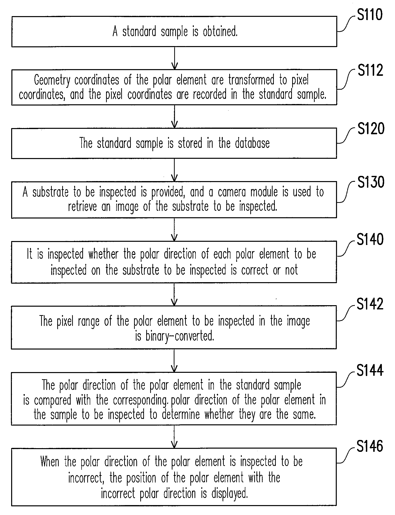
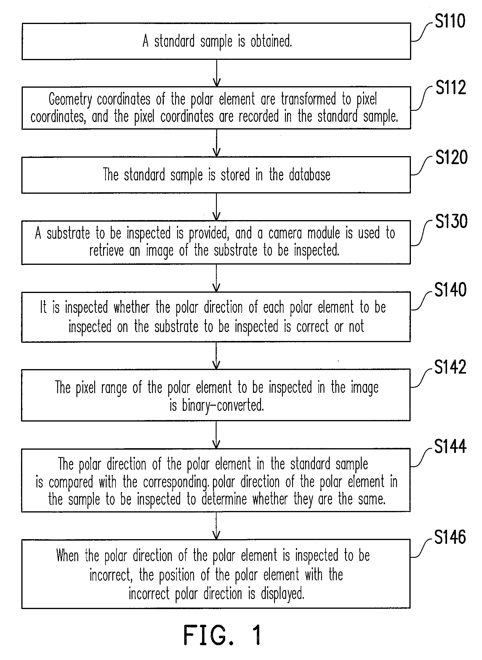
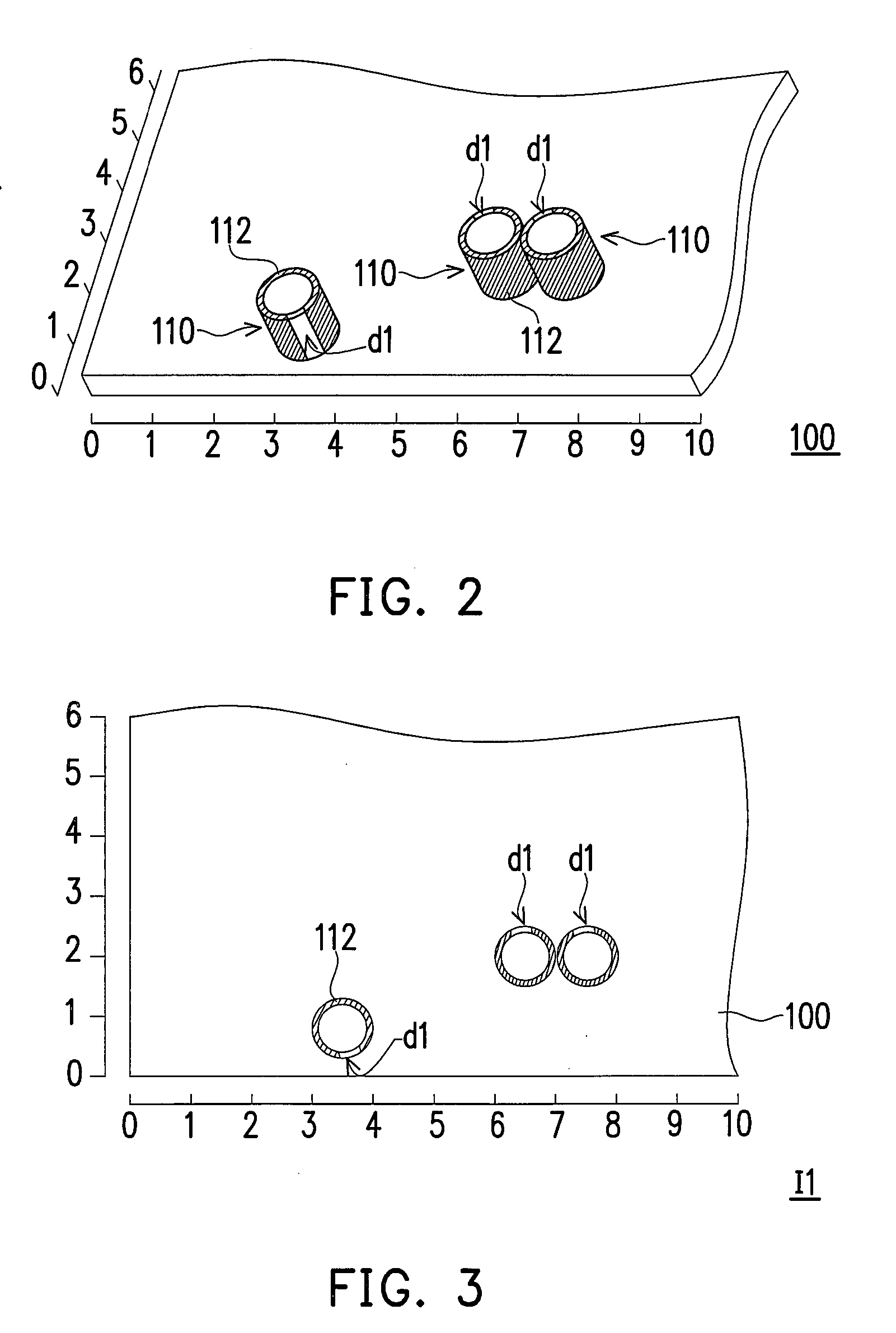
[0028]FIG. 1 is a flow chart of a method for inspecting polar directions of a polar element according to the present invention, FIG. 2 is a partial schematic view of a standard substrate according to the present embodiment, and FIG. 3 is a schematic view of an image of the standard substrate of FIG. 2. Referring to FIG. 1, FIG. 2 and FIG. 3, first, in Step S110, a standard sample is obtained, and the method for obtaining the standard sample includes that an image I1 of a standard substrate 100 is retrieved, and then, position coordinates and polar directions of a plurality of polar elements disposed on the standard substrate is recorded as a standard sample. In the present embodiment, the standard substrate 100 is a motherboard, and a plurality of electronic elements or other polar elements 110 that are required to be inserted by hand are disposed on the standard substrate 100, wherein the polar elements 110 are, for example, DIP electronic elements such as an electrolytic capacitor...


PUM


Abstract

A method for automatically inspecting positive and negative polar directions of a polar element on a substrate is provided. Firstly, an image of a standard substrate is retrieved to form a standard sample, and relevant data of the polar elements on a substrate to be inspected is obtained to form the inspected sample. Then, transforming the geometry coordinates to the pixel coordinates, using different shapes of frames to make each polar element be positioned within, and marking the positions, positive and negative polar directions of all the polar elements in the image of the standard substrate. A database is set up to record the relevant data of each polar element as the standard sample for inspecting. The standard sample is compared with all the samples to be inspected to inspect whether the polar directions of each polar element is correct or not.

Description

CROSS-REFERENCE TO RELATED APPLICATION[0001]This application claims the priority benefit of Taiwan application serial no. 95127439, filed Jul. 27, 2006. All disclosure of the Taiwan application is incorporated herein by reference.BACKGROUND OF THE INVENTION[0002]1. Field of Invention[0003]The present invention relates to a method for inspecting a polar element, and more particularly, to a method for automatically inspecting polar directions of a polar element on a substrate.[0004]2. Description of Related Art[0005]Generally speaking, many electronic elements are assembled on the printed circuit board by automatic assembly equipment.[0006]However, some electronic elements have a voltage polarity requirement. The correct polarity is indicated on the packaging by a stripe with minus signs and possibly arrowheads for the manual visual inspection. This is necessary because a reverse-bias voltage will destroy polar elements. Taking electrolytic capacitors for example, if one electrolytic ...

Claims


Application Information

Patent Timeline
Patent Type & Authority Applications(United States)
IPC IPC(8): G06K9/00G06F19/00
CPCG06T2207/30141G06T7/001
Inventor CHANG, CHUNG-HWASU, HSIN-CHING
Owner ASUSTEK COMPUTER INC
Why Eureka
Try Eureka