Methods and apparatus for centrifuging dry solids

Inactive Publication Date: 2008-01-31
ADVANCED PRODS LAB
View PDF25 Cites 1 Cited by
  • Summary
  • Abstract
  • Description
  • Claims
  • Application Information

AI Technical Summary

Benefits of technology

[0007]The present invention provides a self-cleaning drying centrifuge for removing fluid from a concentrated particulate-filled fluid and peeling mostly dried particulate (solid) material from the centrifuge. In some embodiments, a high-efficiency centrifuge performs an initial separation and concentration of small particles from a contaminated fluid, and outputs a clarified fluid for reuse, and periodically purges concentrated particulates with high fluid content. The purged concentrate is then fed into the present invention's drying centrifuge, which substantially reduces the remaining fluid content. In some embodiments, the drying centrifuge is periodically stopped and one or more internal blades (peelers) are rotated around the inner wall of the drying centrifuge bowl to peel the accumulated solids, which drop into a collection container. In some embodiments, partial peelers are arranged in a balanced configuration, but each peel portions of the bowl not peeled by others, to reduce the brake size needed to hold the bowl.

Problems solved by technology

Slurries, saturated solids, and loaded liquid filters pose significant handling and disposal problems.
Centrifuges designed to discharge nearly dry solids involve complicated and costly construction and high horsepower in order to accomplish their intended function.
The decanter centrifuge has been proven practical in many material processing applications, but because of the complex design is too costly for many liquid clarifying applications.
The plowing process requires high forces to move the blade imbedded in the layer of solids.
The plowed solids still contain a significant quantity of liquid and are wetter than desired in many applications making disposal more troublesome.
Because of wetness of the solids, and the complexity and cost of this class of centrifuges, they are impractical for many clarifying applications.

Method used


Image

  • Methods and apparatus for centrifuging dry solids
  • Methods and apparatus for centrifuging dry solids
  • Methods and apparatus for centrifuging dry solids

Examples


Embodiment Construction

[0037]In the following detailed description, reference is made to the accompanying drawings which form a part hereof, and in which is shown by way of illustration specific illustrative embodiments in which the invention may be practiced. These embodiments are described in sufficient detail to enable those skilled in the art to practice the invention, and it is to be understood that other embodiments may be utilized and that logical, mechanical and electrical changes may be made without departing from the spirit and scope of the present invention. The following detailed description is, therefore, not to be taken in a limiting sense.

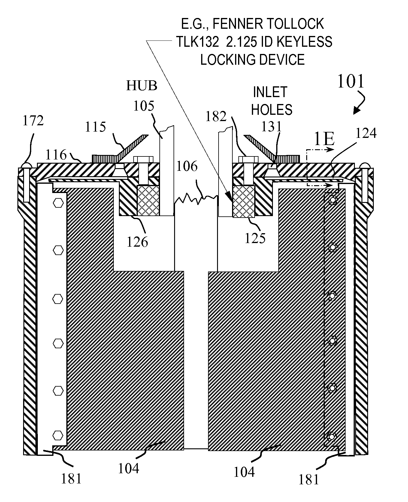
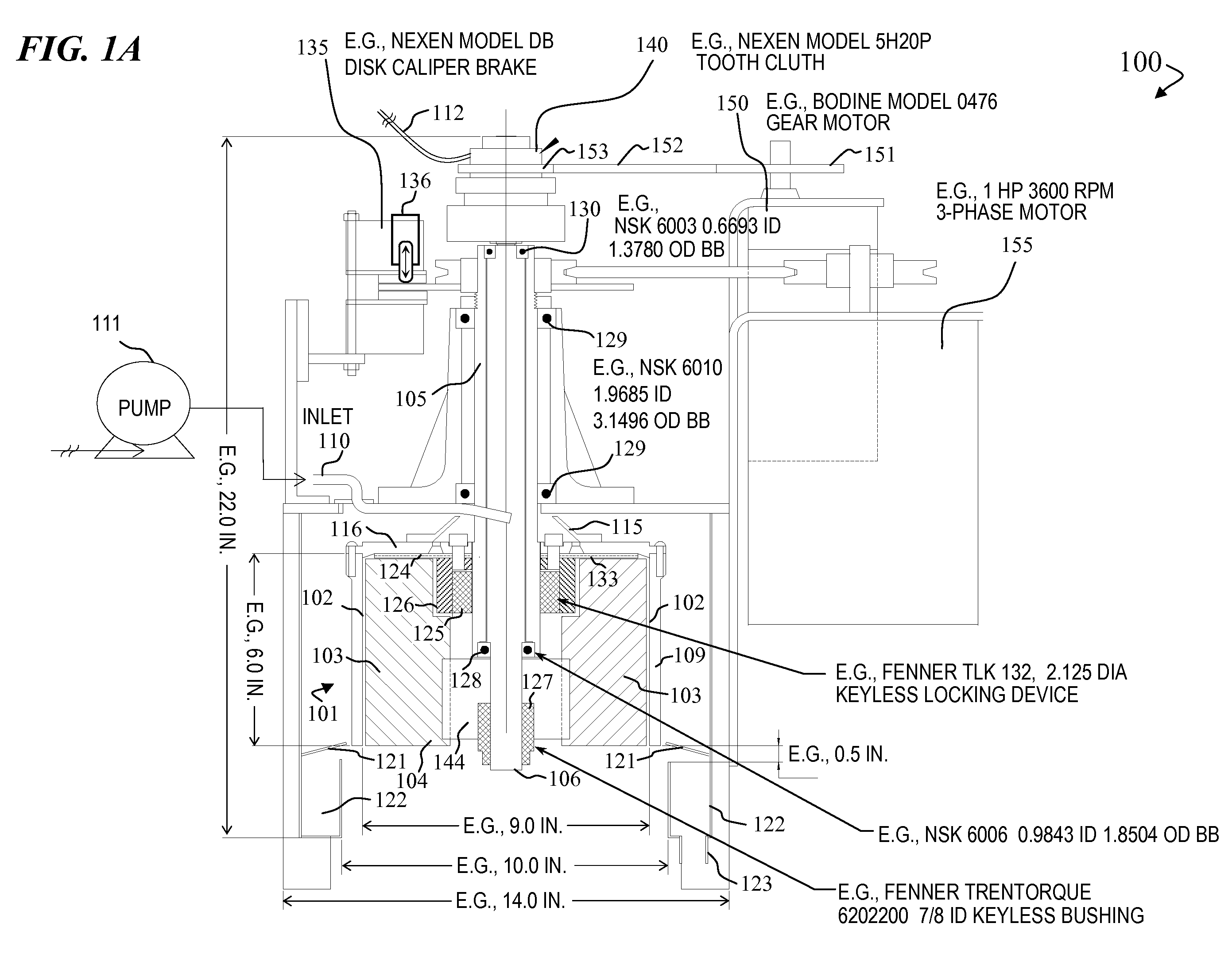
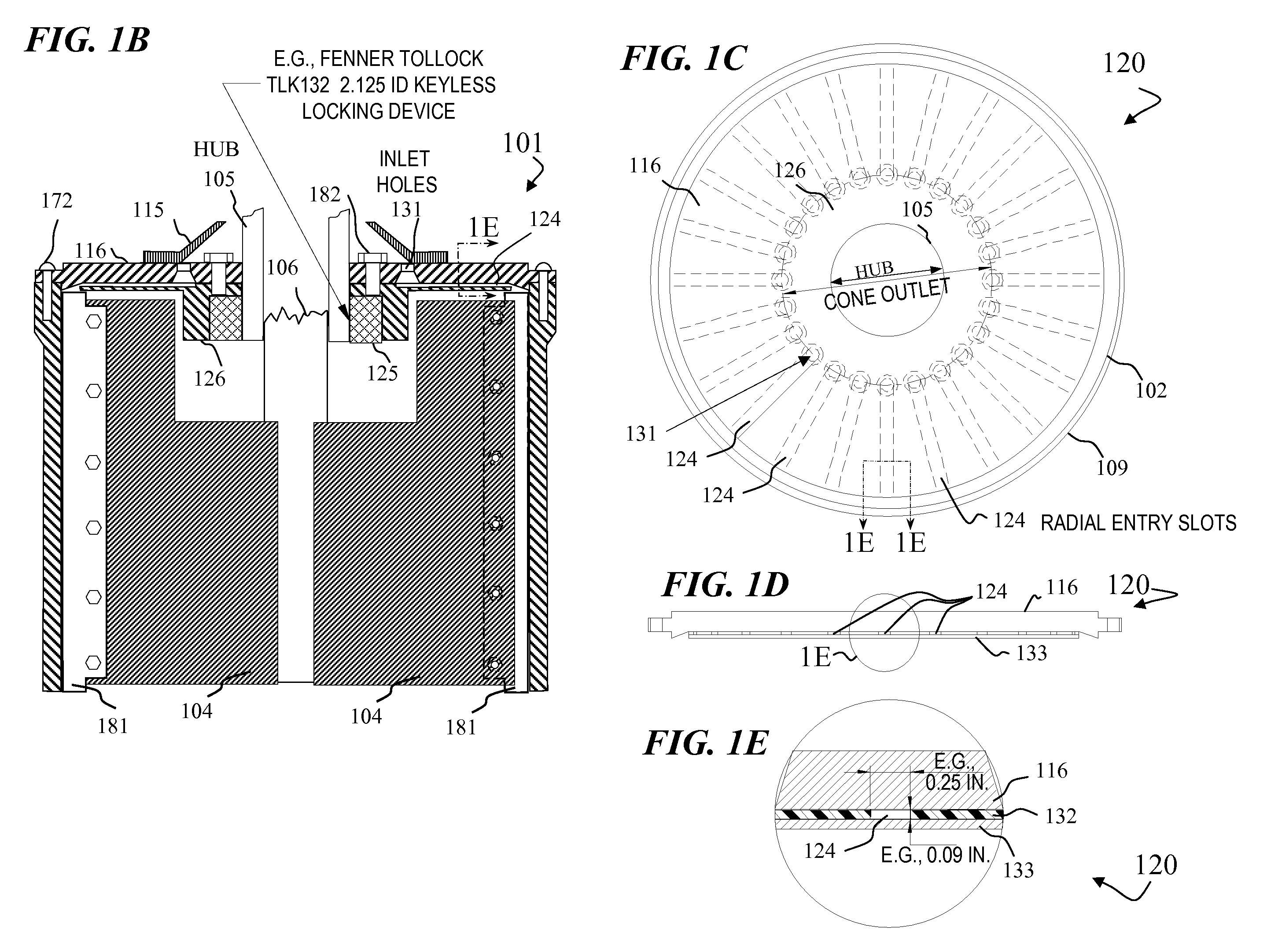
[0038]The present invention provides a centrifuge design for producing dry solids that overcomes the cost and complexity problems associated with conventional centrifuge designs. This type of centrifuge design is called a “dry-solids centrifuge” or “drying centrifuge” since one goal is to remove almost all liquid from a fluid having a concentration of soli...


PUM


Abstract

The present invention provides a self-cleaning drying centrifuge for removing fluid from a concentrated particulate-filled fluid and peeling mostly dried particulate (solid) material from the centrifuge. In some embodiments, a high-efficiency centrifuge performs an initial separation and concentration of small particles from a contaminated fluid, and outputs a clarified fluid for reuse, and periodically purges concentrated particulates with high fluid content. The purged concentrate is then fed into the present invention's drying centrifuge, which substantially reduces the remaining fluid content. In some embodiments, the drying centrifuge is periodically stopped and one or more internal blades (peelers) are rotated around the inner wall of the drying centrifuge bowl to peel the accumulated solids, which drop into a collection container. In some embodiments, partial peelers are arranged in a balanced configuration, but each peel portions of the bowl not peeled by others, to reduce the brake size needed to hold the bowl.

Description

CROSS REFERENCED RELATED APPLICATIONS[0001]This application claims priority to U.S. Provisional Patent Application Ser. No. 60 / 834,246 filed Jul. 31, 2006, which is incorporated herein by reference. This application is also related to U.S. Pat. No. 7,077,799, which is also incorporated herein by reference.FIELD OF THE INVENTION[0002]The present invention relates generally to the field of centrifuging systems. More particularly, the present invention relates to methods and apparatus for economically separating particles from particle-laden fluid and discharging the particulate as dry or nearly dry solids.BACKGROUND OF THE INVENTION[0003]Centrifuges are commonly used for fluid clarification in a wide variety of industrial applications such as grinding, honing, quench oils, thread rolling, vibratory finishing and many others. Some are manually cleaned when loaded with solids. Others discharge the collected solids automatically. Some automatically cleaned centrifuges discharge the solid...

Claims


Application Information

Patent Timeline
IPC IPC(8): B04B11/08
CPCB04B9/08B04B11/08B04B11/04
Inventor DUDREY, DENIS J.GEHRKING, JAMES N.GORHAM, ADELBERTJORGENSON, RONALD L.SPEARS, RODGER I.WEISERT, LLOYD E.
Owner ADVANCED PRODS LAB
Why Eureka
Try Eureka