Encoding Device, Decoding Device, and Method Thereof

a decoding device and encoder technology, applied in the field of encoders and encoders, can solve the problems of difficult to say that the quality is sufficient for services requiring high realistic quality, coding delay becomes substantial, and quality tends to lack realistic quality, so as to improve the subjective quality of encoded signals.

Active Publication Date: 2008-01-31
PANASONIC INTELLECTUAL PROPERTY CORP OF AMERICA
View PDF34 Cites 44 Cited by
  • Summary
  • Abstract
  • Description
  • Claims
  • Application Information

AI Technical Summary

Benefits of technology

[0017] According to the present invention, in a technology of substituting a spectrum of another band for a spectrum of given band, it

Problems solved by technology

Though these schemes are capable of coding at a low bit rate, since the targeted narrow band signal is narrow up to a maximum of 3.4 kHz, this quality tends to lack realistic quality.
From the viewpoint of speech quality, wideband speec

Method used


Image

  • Encoding Device, Decoding Device, and Method Thereof
  • Encoding Device, Decoding Device, and Method Thereof
  • Encoding Device, Decoding Device, and Method Thereof

Examples


embodiment 1

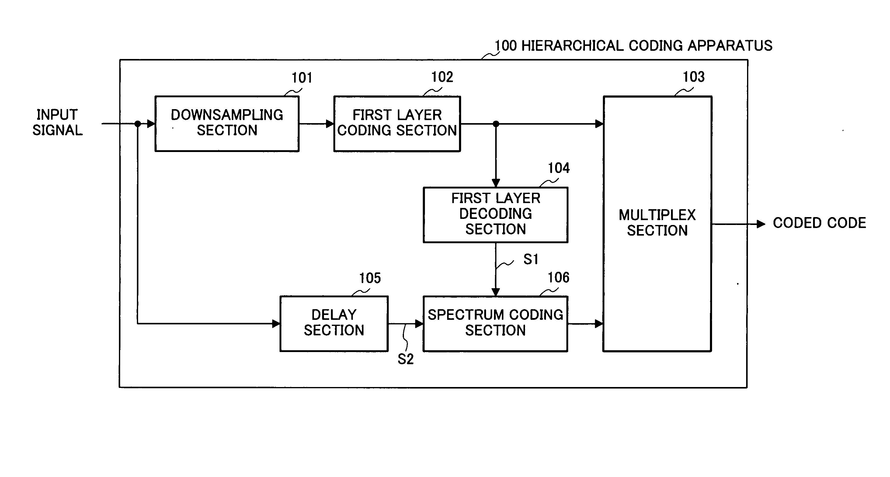
[0048]FIG. 3 is a block diagram showing the main configuration of hierarchical coding apparatus 100 according to Embodiment 1 of the present invention. Here, a case will be explained as an example where coding information has a hierarchical structure made up of a plurality of layers, that is, hierarchical coding (scalable coding) is performed.

[0049] Each part of hierarchical coding apparatus 100 carries out the following operation in accordance with input of the signal.

[0050] Down-sampling section 101 generates a signal with a low sampling rate from the input signal and supplies this signal to first layer coding section 102. First layer coding section 102 codes the signal outputted from down-sampling section 101. Coded code obtained at first layer coding section 102 is supplied to multiplex section 103 and to first layer decoding section 104. First layer decoding section 104 then generates first layer decoding signal S1 from the coded code outputted from first layer coding section...

embodiment 2

[0112] In Embodiment 2 of the present invention, a second spectrum is estimated using a pitch filter having a first spectrum as an internal state, and the characteristics of this pitch filter are coded.

[0113] The configuration of the hierarchical coding apparatus according to this embodiment is the same as the hierarchical coding apparatus shown in Embodiment 1, and therefore spectrum coding section 201 which has a different configuration will be explained using the block diagram of FIG. 11. Components that are identical with spectrum coding section 106 (refer to FIG. 4) shown in Embodiment 1 will be assigned the same reference numerals without further explanations.

[0114] Internal state setting section 203 sets internal state S(k) of a filter used at filtering section 204 using modified first spectrum S1′(k) generated at spectrum modification section 112.

[0115] Filtering section 204 carries out filtering based on internal state S(k) of the filter set at internal state setting sec...

embodiment 3

[0148]FIG. 14 is a block diagram showing the main configuration of a spectrum coding section according to Embodiment 3 of the present invention. In FIG. 14, blocks assigned with the same names and same reference numerals as in FIG. 4 have the same functions, and therefore explanations will be omitted. In Embodiment 3, the dynamic range of the spectrum is adjusted based on common information between the coding side and the decoding side. By this means, it is not necessary to output coded code indicating a dynamic range adjustment coefficient for adjusting the dynamic range of the spectrum. It is not necessary to output coded code indicating the dynamic range adjustment coefficient, so that a bit rate can be reduced.

[0149] Spectrum coding section 301 in FIG. 14 has dynamic range calculating section 302, modification information estimating section 303 and modification section 304 between frequency domain converting section 111 and extension frequency band spectrum coding section 114 i...


PUM


Abstract

There is disclosed an encoding device capable of appropriately adjusting the dynamic range of spectrum inserted according to the technique for replacing a spectrum of a certain band with a spectrum of another band. The device includes a spectrum modification unit (112) which modifies a first spectrum S1(k) of the band 0≦k<FL in various ways to change the dynamic range so that a way of modification for obtaining an appropriate dynamic range is checked. The information concerning the modification is encoded and given to a multiplexing unit (115). By using a second spectrum S2(k) having a valid signal band 0≦k.

Description

TECHNICAL FIELD [0001] The present invention relates to a coding apparatus and decoding apparatus that codes / decodes a speech signal, audio signal and the like, and methods thereof. BACKGROUND ART [0002] A speech coding technology that compresses a speech signal at a low bit rate is important for efficiently using a radio wave etc. in mobile communication. Further, in recent years, expectation for improvement of quality of communication speech has been increased, and it is desired to implement communication services with high realistic quality. Here, realistic quality means the sound environment surrounding the speaker (for example, BGM), and it is preferable that signals other than a speech signal such as audio can be coded with high quality. [0003] There are schemes such as G726 and G729 defined in ITU-T (International Telecommunication Union Telecommunication Standardization Sector) for speech coding of coding speech signals. In these schemes, coding is carried out at 8 kbit / s to...

Claims


Application Information

Patent Timeline
IPC IPC(8): G10L19/00G10L19/02G01L21/04G10L19/032G10L21/0388H03M7/30
CPCG10L21/0364G10L19/0208G10L21/0332G10L21/038G10L19/02G10L19/06
Inventor OSHIKIRI, MASAHIROEHARA, HIROYUKI
Owner PANASONIC INTELLECTUAL PROPERTY CORP OF AMERICA
Why Eureka
Try Eureka