Method and Apparatus For Refresh Management of Memory Modules

a memory module and memory module technology, applied in the field of memory modules, can solve the problem that the higher capacity may draw large electrical currents

Inactive Publication Date: 2008-01-31
GOOGLE LLC
View PDF96 Cites 184 Cited by
  • Summary
  • Abstract
  • Description
  • Claims
  • Application Information

AI Technical Summary

Benefits of technology

[0009]One embodiment sets forth an interface circuit configured to manage refresh command sequences. The interface circuit includes a system interface adapted to receive a refresh command from a memory controller, clock frequency detection circuitry configured to determine the timing for issuing staggered refresh commands to two or more memory devices coupled to the interface circuit based on the refresh command received from the memory controller, and at least two refresh command sequence outputs configured to generate the staggered refresh commands for the two or more memory devices.

Problems solved by technology

However, one issue associated with the action of refreshing more DRAM devices for each refresh operation in the higher capacity DRAM devices is that larger electrical currents may be drawn by the higher capacity DRAM devices for each refresh operation.

Method used


Image

  • Method and Apparatus For Refresh Management of Memory Modules
  • Method and Apparatus For Refresh Management of Memory Modules
  • Method and Apparatus For Refresh Management of Memory Modules

Examples


Embodiment Construction

[0029]Illustrative information will now be set forth regarding various optional architectures and features of different embodiments with which the foregoing frameworks may or may not be implemented, per the desires of the user. It should be strongly noted that the following information is set forth for illustrative purposes and should not be construed as limiting in any manner. Any of the following features may be optionally incorporated with or without the other features described.

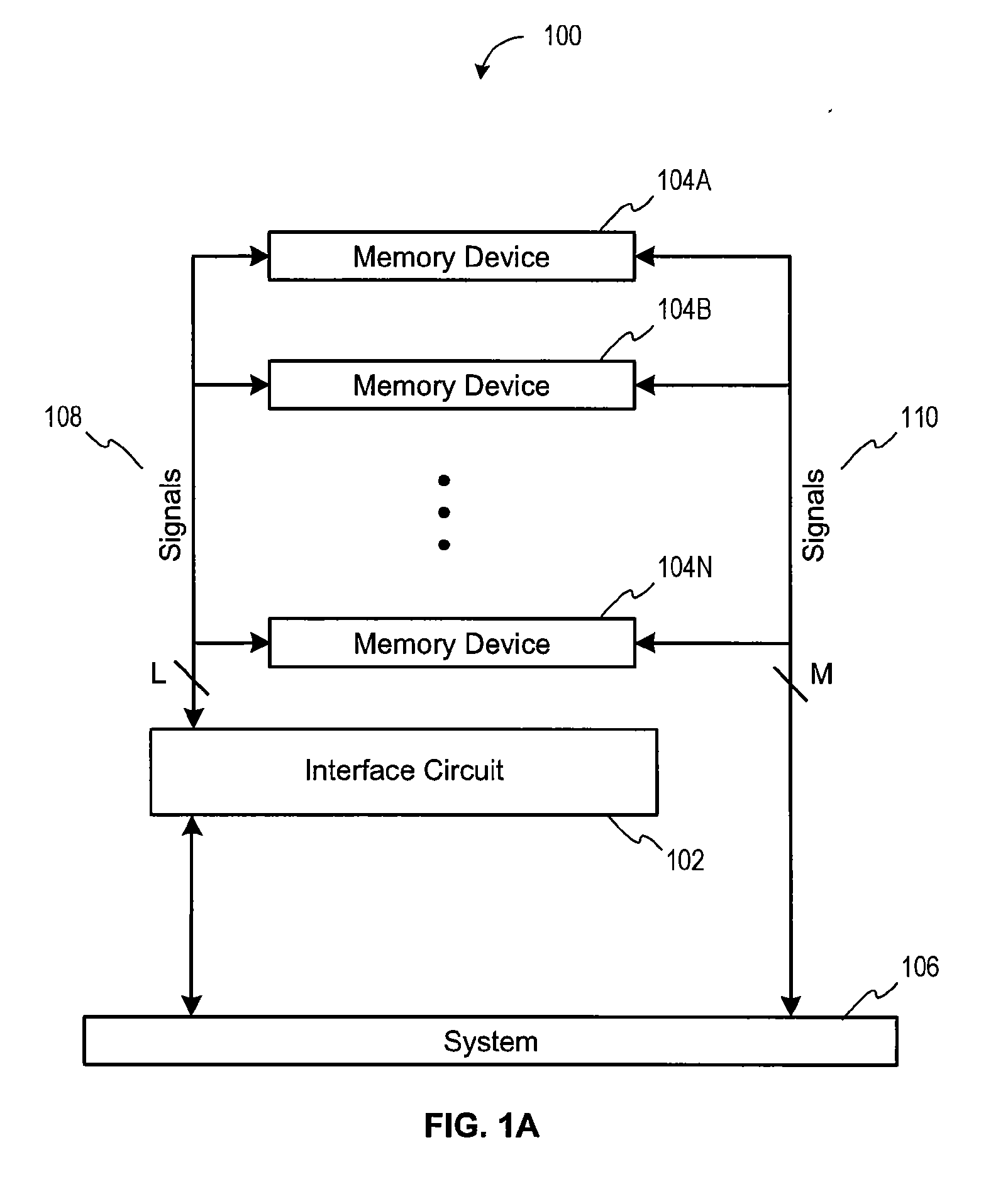
[0030]FIG. 1A illustrates a multiple memory device system 100, according to one embodiment. As shown, the multiple memory device system 100 includes, without limitation, a system device 106 coupled to an interface circuit 102, which is, in turn, coupled to a plurality of physical memory devices 104A-N. The memory devices 104A-N may be any type of memory devices. For example, in various embodiments, one or more of the memory devices 104A, 104B, 104N may include a monolithic memory device. For instance, suc...


PUM


Abstract

One embodiment sets forth an interface circuit configured to manage refresh command sequences that includes a system interface adapted to receive a refresh command from a memory controller, clock frequency detection circuitry configured to determine the timing for issuing staggered refresh commands to two or more memory devices coupled to the interface circuit based on the refresh command received from the memory controller, and at least two refresh command sequence outputs configured to generate the staggered refresh commands for the two or more memory devices

Description

CROSS-REFERENCE TO RELATED APPLICATIONS[0001]This application is a continuation-in-part of the U.S. patent application having Ser. No. 11 / 584,179, filed on Oct. 20, 2006, which is a continuation of the U.S. patent application having Ser. No. 11 / 524,811, filed on Sep. 20, 2006, which is a continuation-in-part of the U.S. patent application having Ser. No. 11 / 461,439, filed on Jul. 31, 2006. The current application also claims the priority benefit of U.S. Provisional Patent Application No. 60 / 823,229, filed on Aug. 22, 2006. The subject matter the above related applications is hereby incorporated herein by reference. However, insofar as any definitions, information used for claim interpretation, etc. from the above parent application conflict with that set forth herein, such definitions, information, etc. in the present application should apply.BACKGROUND OF THE INVENTION[0002]1. Field of the Invention[0003]Embodiments of the present invention generally relate to memory modules and, m...

Claims


Application Information

Patent Timeline
Patent Type & Authority Applications(United States)
IPC IPC(8): G06F13/28
CPCG11C7/04G11C11/40618G11C11/40611G11C11/406
Inventor SCHAKEL, KEITH R.RAJAN, SURESH NATARAJANSEBASTIAN SMITH, MICHAEL JOHNWANG, DAVID T.
Owner GOOGLE LLC
Why Eureka
Try Eureka