
Stackable rebar support chair

a rebar support and seat technology, applied in the direction of building components, building reinforcements, constructions, etc., can solve the problems of lack of centering support and failure to provide a stackable rebar support chair, and achieve the effect of facilitating proper weight distribution and alignment and additional structural rigidity

Inactive Publication Date: 2008-02-07
EAGLE EYE PRODS
View PDF45 Cites 64 Cited by
  • Summary
  • Abstract
  • Description
  • Claims
  • Application Information

AI Technical Summary

Benefits of technology

[0004]In one embodiment of the invention there is at least one centering support connected to and extending between each of the upstanding posts and the upper surface of the base. Each of the centering supports is designed to permit gravity to assist the supported rebar to a generally central position on the base, thereby facilitating proper weight distribution and alignment. Additionally, the centering supports reinforce the upstanding posts when the rebar support chairs are stacked on top of each other. In another embodiment of the invention, there are multiple centering supports connected to and extending between each of the upstanding posts and the base.
[0005]In another example embodiment of the invention, the base can include at least one hole extending through it to permit the free flow of concrete, cement or any other type of construction material. In another embodiment of the invention there are multiple holes extending through the base such that at least a pair of cross supports is formed extending between the upstanding posts and legs. In this embodiment of the invention, centering supports can be attached to and can extend between the upstanding posts and the cross supports. Additionally, ribs may be positioned on a lower surface of the base, and / or base and cross supports to provide additional structural rigidity.

Problems solved by technology

However, all of these devices fail to provide a stackable rebar support chair having centering supports designed to automatically position the rebar on the support chair.
They also lack centering supports that are designed to support upstanding posts that are used to stack multiple support chairs on top of each other.

Method used


Image

  • Stackable rebar support chair
  • Stackable rebar support chair
  • Stackable rebar support chair

Examples


Embodiment Construction

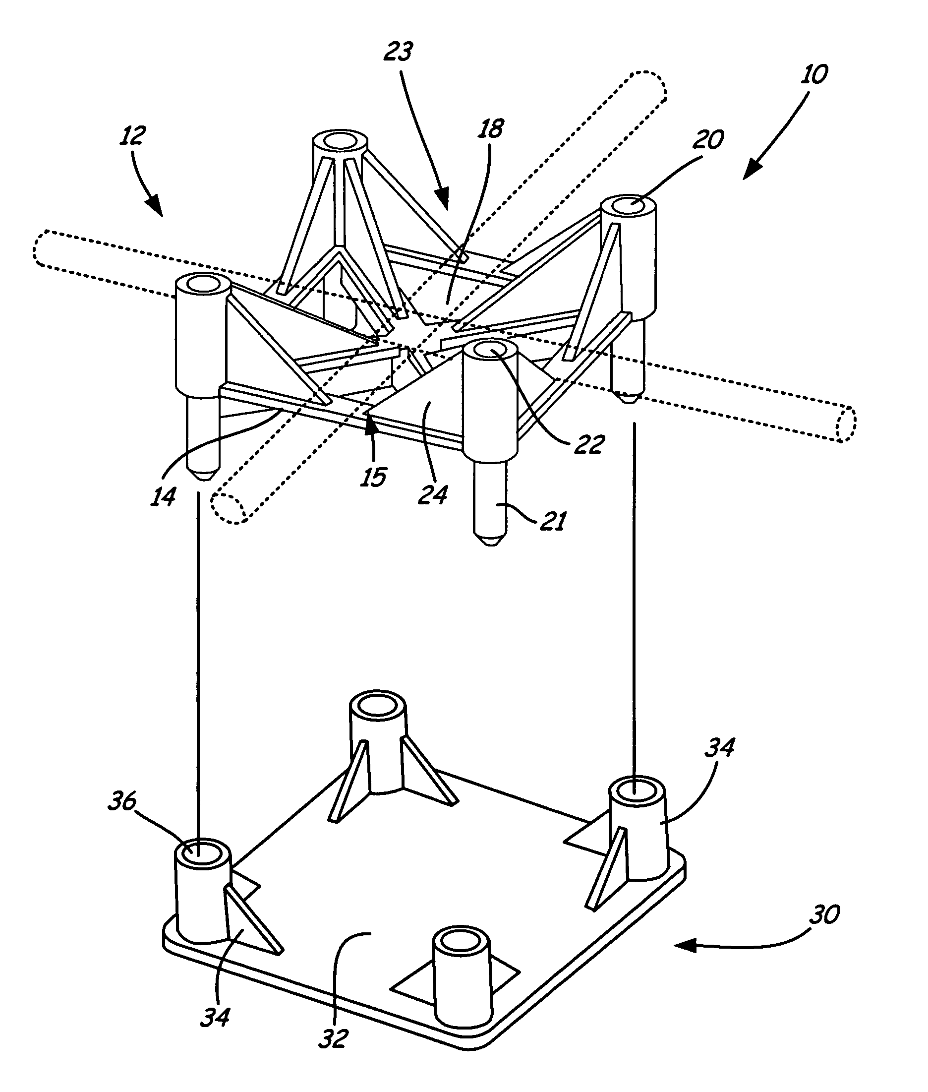
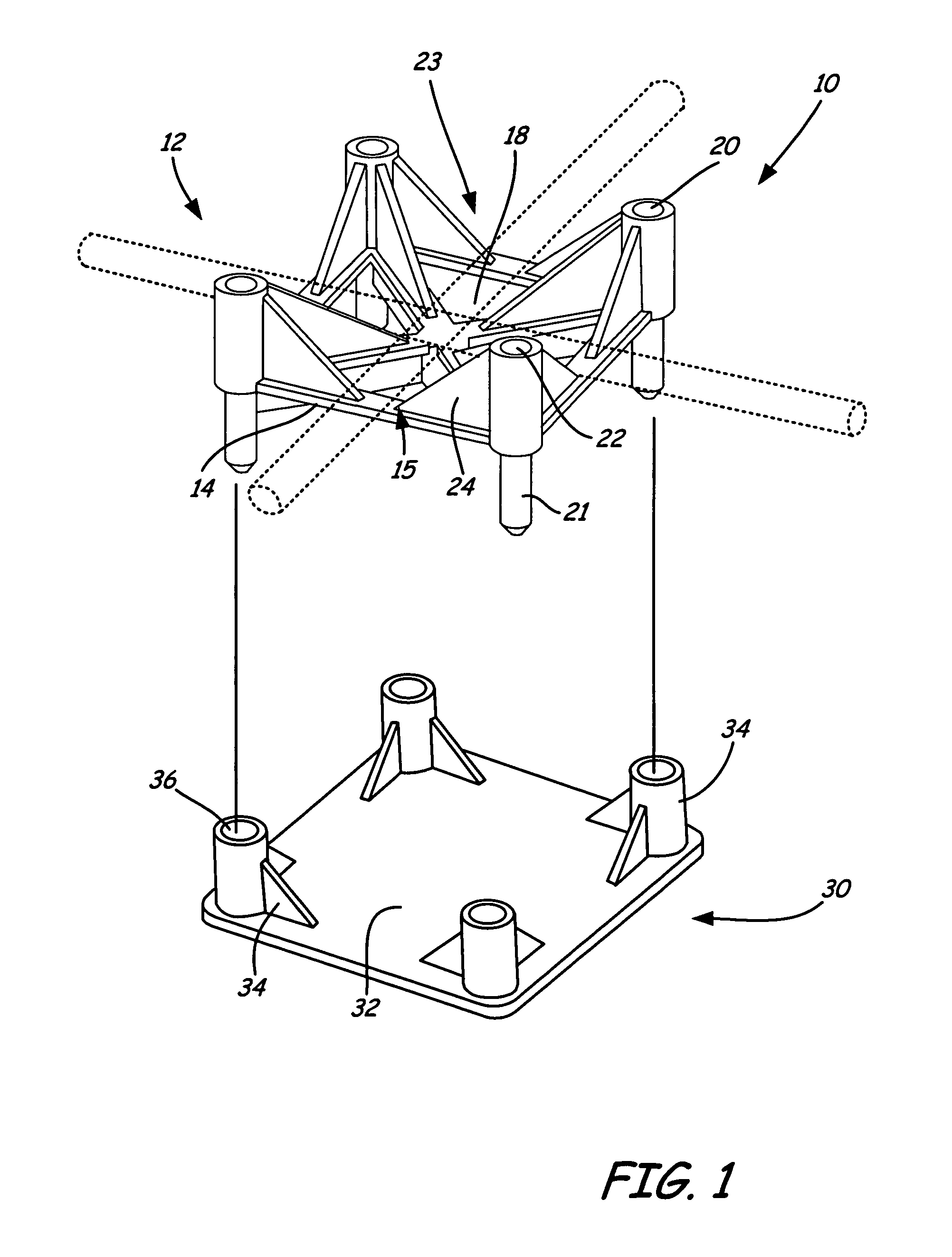
[0020]Referring to FIGS. 1-10, a stackable rebar support chair, noted by the numeral 10 is provided for supporting rebar above a surface such as dirt, rocks, sand, and the like. Referring to FIG. 1, the stackable rebar support chair 10 includes a chair support 12 and a support plate 30 made of a generally rigid material such as plastic or metal. However, any type of material capable of supporting rebar and other construction materials can be utilized. In one example embodiment, the chair support 12 and the support plate 30 can be detachably coupled together for supporting rebar on soft surfaces such as sand. However, the support chair 12 can also be used without the support plate 30 to support rebar or other construction materials above harder surfaces such as rock, cement or concrete.

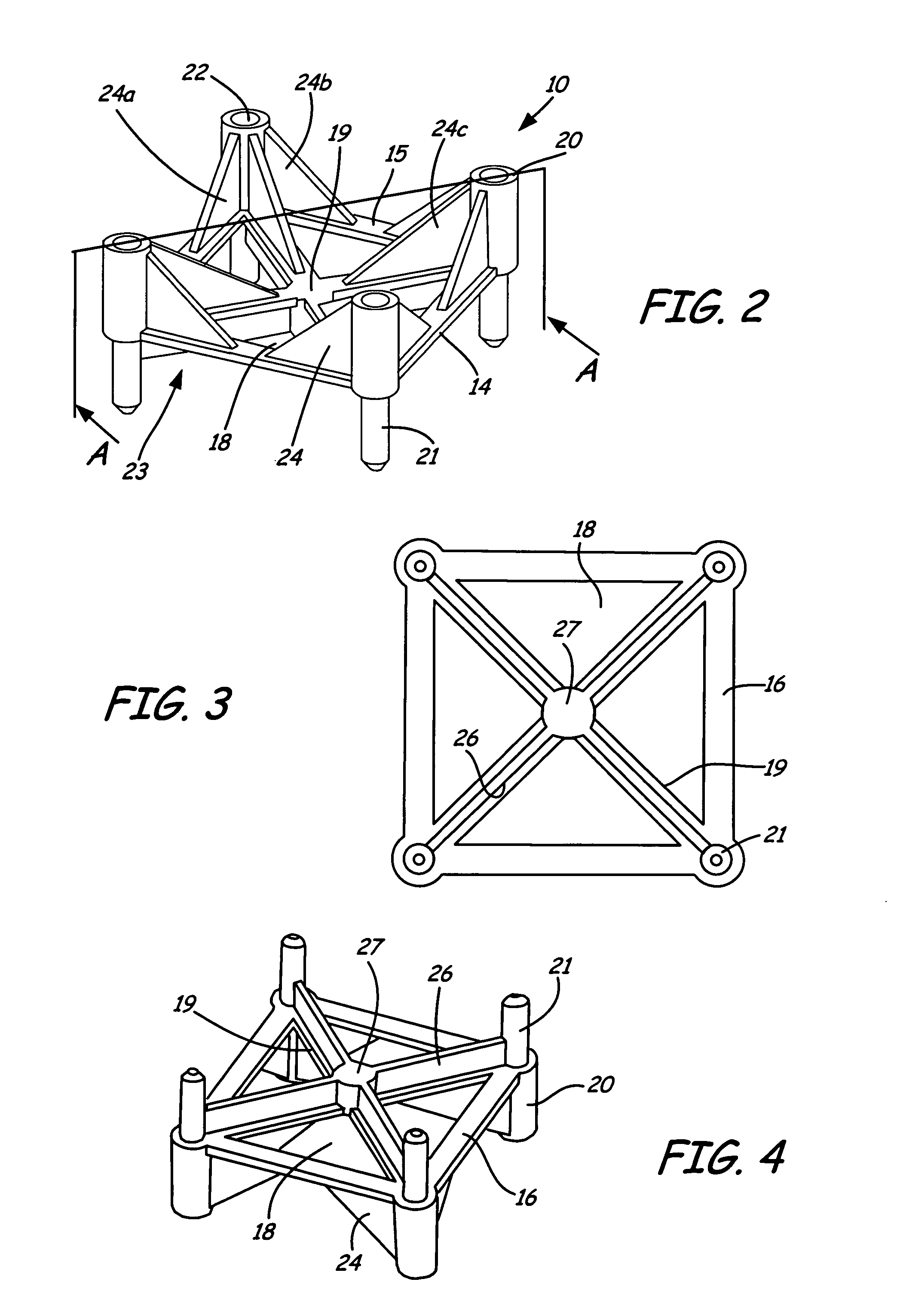
[0021]Referring now to FIG. 2, the support chair 12 includes a base 14 that is oriented generally horizontal to the surface or ground. The base includes an upper surface 15 and a lower surface 16 orien...


PUM


Abstract

A stackable rebar support chair having a support chair and a support plate detachable to each other. The support chair includes a base having multiple upstanding posts and downwardly extending legs designed to suspend the base above surface. The base can include multiple holes to permit the free flow of concrete around the support chair. Multiple centering supports can connect to and extend between each of the upstanding posts and an upper surface of the base to provide support to the posts and to permit gravity to assist positioning the supported rebar to a generally central position on the base. The base can include ribs extending from its lower surface to provide support to the base from the weight of the rebar. The support plate can include multiple generally upright pegs having recesses to receive the legs.

Description

FIELD OF THE INVENTION[0001]The present invention relates generally to an apparatus for positioning and supporting rebar and other reinforcement devices a distance above a surface. More specifically, the invention relates to a stackable rebar support chair having centering supports designed to automatically position the rebar on the support chair and to support upstanding posts used to stack multiple support chairs.BACKGROUND OF THE INVENTION[0002]The use of various rebar support chair devices is known in the prior art. However, all of these devices fail to provide a stackable rebar support chair having centering supports designed to automatically position the rebar on the support chair. They also lack centering supports that are designed to support upstanding posts that are used to stack multiple support chairs on top of each other.BRIEF SUMMARY OF THE INVENTION[0003]The invention in particular embodiments has base having a number of legs extending downwardly from a lower surface a...

Claims


Application Information

Patent Timeline
IPC IPC(8): E04C5/16
CPCE04C5/206
Inventor ERICKSON, JOHN A.ANDERSON, KEVIN
Owner EAGLE EYE PRODS
Features
  • Generate Ideas
  • Intellectual Property
  • Life Sciences
  • Materials
  • Tech Scout
  • Unparalleled Data Quality
  • Higher Quality Content
  • 60% Fewer Hallucinations
Learn More