

Liquid dispenser
a dispenser and liquid technology, applied in the direction of liquid transferring devices, single-unit apparatuses, pliable tubular containers, etc., can solve the problems of inability to output liquid in any direction, complex structure, and inability to compact construction
- Summary
- Abstract
- Description
- Claims
- Application Information
AI Technical Summary
Benefits of technology
Problems solved by technology
Method used
Image

Examples
embodiment 1
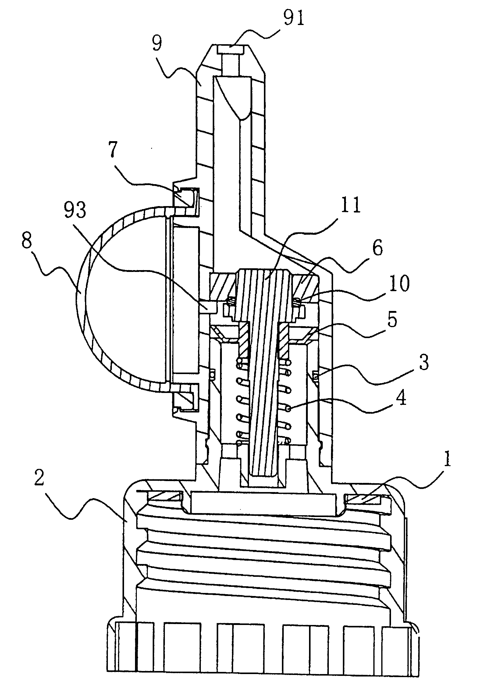
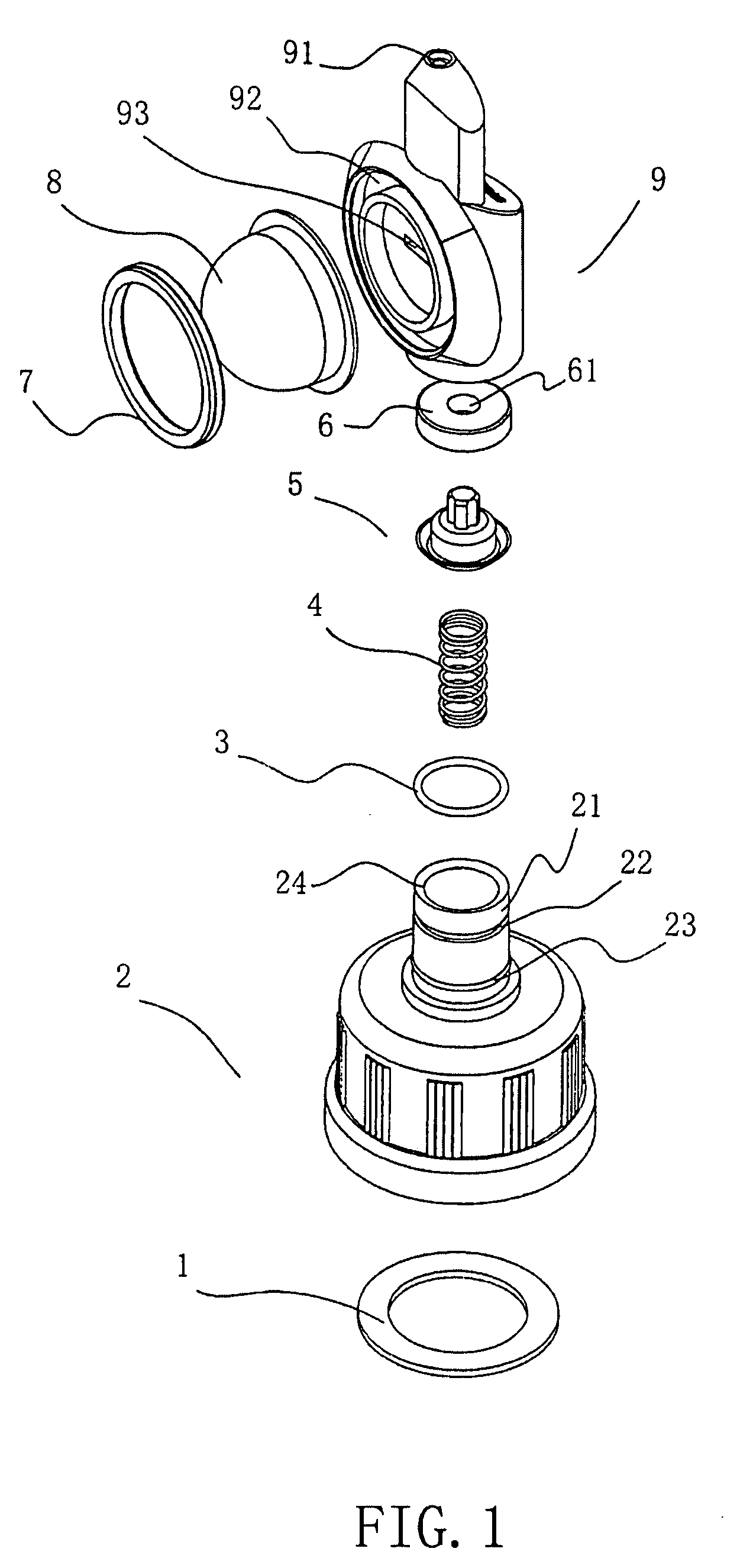
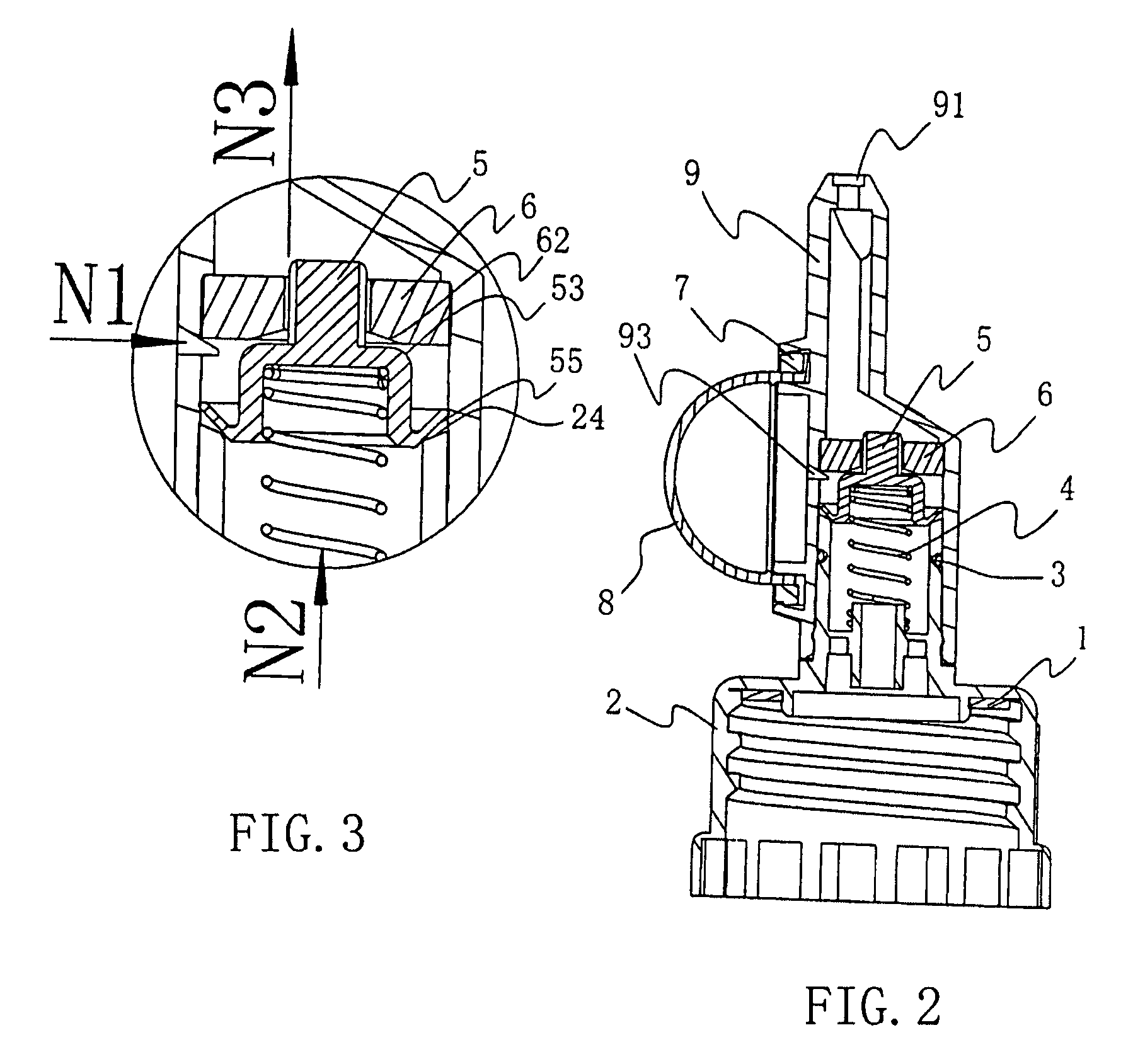
[0039]Please refer to FIG. 1, this novel liquid dispenser mainly includes cover 2, main body 9 and liquid output device comprising button 8, water-sealing ring 6 and spring 4, and valve plate 5 with the effect of a 2-in-1 one-way valve, etc., wherein:
[0040]Cover 2 engages with the opening of the container and in the cover 2 there is a padding piece 1 to ensure it is sealed with the container. On the top of the cover 2 there is a circular tube 21 for connecting to the main body. On the circular tube 21 there is an annular slot 22 for embedding O-shaped sealing ring and an annular flange 23 buckled with the main body.
[0041]The main body 9 is hollow. The inner wall of the lower part of the main body is rotationally engaged with the outer wall of the circular tube 21 of the cover and on the inner wall of the main body 9. There is an annular slot that can connect the main body 9 to the circular tube 21, such as by being buckled with the annular flange 23 of the cover. Said main body 9 is...
embodiment 2
[0046]The liquid dispenser as shown in FIG. 10-FIG. 12, the construction of liquid output device and valve adopted by this embodiment 2 is different from embodiment 1. The liquid output device in this embodiment is composed of button 8, piston 11, water-sealing ring 6 and spring 4, etc. The valve plate 5 also has the function of one-way valve. Its main body is also made into a plate-like shape to match with main body 9. Specifically, the valve plate 5 comprises a circular tube 56 for configuring with piston 11. The outward extension of the circular tube 56 is equipped with a plate-like annular plane 57 which can sealingly engage with the opening 24 of the cover 2. The valve plate 5 is assembled with the piston 11. The piston 11 is coupled through the valve plate 5. The valve plate 5 can close or open the opening 24 of the circular tube 21 of the cover 2. The piston 11 is a component which has a cross-like cross-section area, its upper part is inserted in the opening of the water-sea...
embodiment 3
[0048]This embodiment is modified on the basis of the embodiment 1. By modifying the structure of the valve plate and performing certain adaptive changes to the cover and the main body, the spring and the inner side of the valve plate can be kept out of reach of the liquid when the dispenser is discharging liquid. This can not only increase the flexibility of the product operation but also ensure the liquid quality is not affected and it is also good in terms of safety.
[0049]Specifically, as shown in FIG. 13-FIG. 15, the valve plate 5 as shown in the drawings of this embodiment is made on the basis of the valve plate in the embodiment 1 and further extend upward and downward from its upper part and lower part respectively a circular tube 58, 59, and a chamber 94 is formed in the main body 9 and receivable of the upper circular tube 58. A n opening 95 is arranged at the top part of the chamber. The upper circular tube 58 is inserted in the chamber 94 and its outer wall sealingly enga...
PUM
 Abstract
Description
Claims
Application Information