Electronic device with pad height adjustable

a technology of electronic devices and pad height, which is applied in the direction of machine frames, kitchen equipment, stand/trestles, etc., can solve the problems of many limits, increase of fabricating costs, and unnecessary troubles for users, and achieve the effect of occupying a lot of disposing spa

Inactive Publication Date: 2008-02-07
INVENTEC MULTIMEDIA & TELECOM
View PDF0 Cites 17 Cited by
  • Summary
  • Abstract
  • Description
  • Claims
  • Application Information

AI Technical Summary

Benefits of technology

[0008]In view of the above, the present invention provides an electronic device with pad height adjustable, so as to improve the disadvantages in the prior art that it takes too much time to adjust the height of the foot and a lot of disposing space is occupied.

Problems solved by technology

The method of adjusting the height of each foot is to rotate each plastic pad to the same height, such that the IP phone can lie stably, so it takes too much time to adjust each pad to the same height, which does not deviate from the efficiency requirement of the current society, but also causes unnecessary troubles to the user.
Moreover, the manner of adopting a supporting foot rest may result in the increase of the fabricating cost and taking too much disposing space while the height thereof can not be adjusted, which causes many limits when the user selects the disposing position and is quite inconvenient.
For the foot of the conventional art, the height thereof can not be quickly and precisely adjusted, so the user has to spend plenty of time adjusting the height and the tilt angle of the phone; for the supporting foot rest of the conventional art, the height thereof can not be changed and the disposing space is too large, which depart from the practical demands.

Method used


Image

  • Electronic device with pad height adjustable
  • Electronic device with pad height adjustable
  • Electronic device with pad height adjustable

Examples


first embodiment

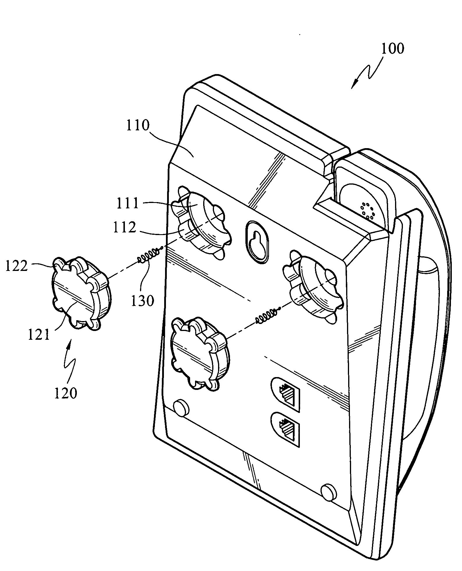
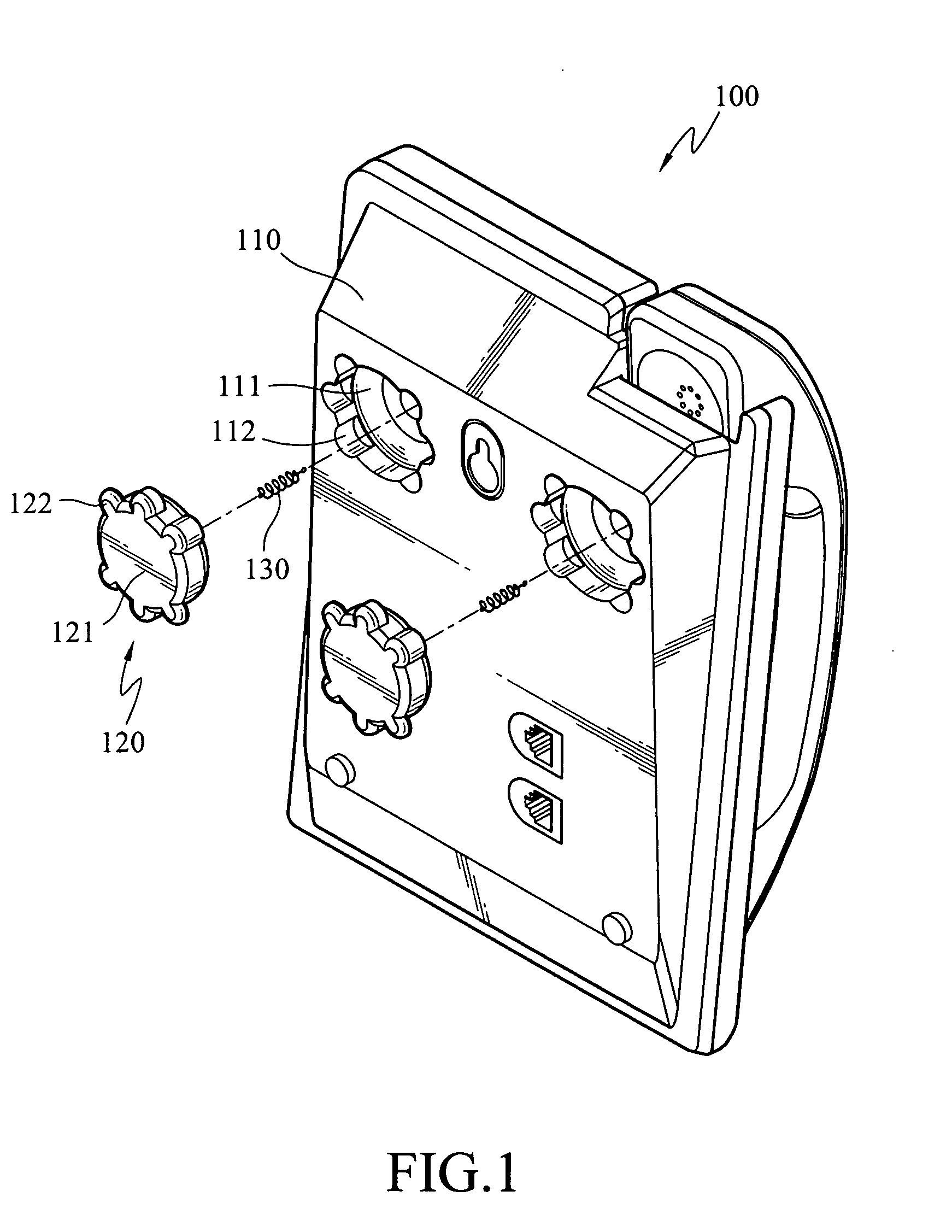
[0028]FIG. 1 is a schematic exploded view of the present invention. As shown in the figure, an electronic device with pad height adjustable 100 comprises a housing 110, a foot 120 and an elastomer 130. The foot 120 has a body 121 and a plurality of pads 122 formed in the body 121. An accommodating hole 111 is formed in the back of the housing 110 of the electronic device 100, and a plurality of notches 112 is formed in the radial direction along the edge of the accommodating hole 111. The body 121 is disposed in the accommodating hole 111. When the body 121 is accommodated in the accommodating hole 111, at least one of the pads 122 selectively presses against the housing 110, and the rest of the pads 122 are respectively nested in each of the notches 112, so as to make a part of the body 121 protrude from the surface of the housing 110. Further, the thickness of each pad 122 is not equal to the thickness of the rest of the pads 122, so when different pads 122 press against the housi...

second embodiment

[0033]FIG. 5 is a schematic exploded view of the present invention. It is shown in the figure that the electronic device with pad height adjustable 100 comprises a housing 110, a foot 120 and an elastomer 130. The foot 120 has a body 121 and a pad 122 formed in the body 121. An accommodating hole 111 is formed in the back of the housing 110 of the electronic device 100, and a plurality of notches 112 is formed in the radial direction along the edge of the accommodating hole 111. The body 121 is disposed in the accommodating hole 111. When the body 121 is accommodated in the accommodating hole 111, the pad 122 selectively presses against a notch 112 of the accommodating hole 111, so as to make a part of the body 121 protrude from the surface of the housing 110. Further, the thickness of each notch 112 is not equal to the thickness of the rest of the notches 112. Therefore, when the pad 122 presses against different notches 112, the height of the body 121 protruding from the surface o...


PUM


Abstract

An electronic device with pad height adjustable is provided. The device includes a housing with an accommodating hole and a foot with a body and at least one pad. The body is disposed in the accommodating hole and presses against the housing with one of the pads, such that the body protrudes from the surface of the housing. Moreover, a plurality of notches is formed at the outer edge of the accommodating hole, so as to accommodate the rest of the pads. A user can adjust the foot to different heights on various demands.

Description

BACKGROUND OF THE INVENTION[0001]1. Field of Invention[0002]The present invention relates to a pad of an electronic device. More particularly, the present invention relates to an electronic device with pad height adjustable, wherein the height of the foot protruding from the electronic device is changed to adjust different tilt angles of the electronic device.[0003]2. Related Art[0004]Along with the development and popularization of science and technology, each family has many electronic products, such as personal computer, notebook, city phone or internet protocol phone (IP phone), which make the life of the people more convenient. In order to put the electronic products stably on a table or on the ground, a plurality of feet is installed on the bottom of the electronic products to increase the friction against the table or the ground, so as to balance and stably support the electronic devices, thus preventing the electronic products from directly contacting the disposing plane or ...

Claims


Application Information

Patent Timeline
Patent Type & Authority Applications(United States)
IPC IPC(8): A47B91/00F16M11/20
CPCF16M7/00F16M11/24F16M11/046F16M13/02F16M11/105F16M11/22F16M13/005F16M11/10
Inventor HSU, KAO-YU
Owner INVENTEC MULTIMEDIA & TELECOM
Why Eureka
Try Eureka