Method for placing material onto a target board by means of a transfer board
a transfer board and material technology, applied in the direction of printed circuit manufacturing, conductive pattern formation, solid-state devices, etc., can solve the problems of increasing difficulty in reliable and reproducible dense material placement, slow and error-prone procedures, short circuit or malfunction of devices, etc., to improve the effect of the integrated circui
- Summary
- Abstract
- Description
- Claims
- Application Information
AI Technical Summary
Benefits of technology
Problems solved by technology
Method used
Image

Examples
first embodiment
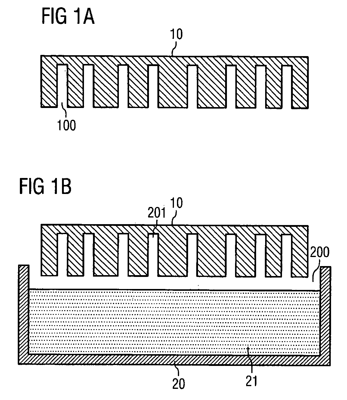
[0026]FIG. 1A shows a transfer board 10 comprising blind holes 100 according to the present invention. The plurality of blind holes 100 may thereby extend along an entire surface of the transfer board 10. In general, the position of each blind hole 100 is chosen in such a way that it corresponds to the position of the material to be placed on a target board. To meet present-day demands, the diameter of a blind hole 100 is usually less than 10 μm, and the minimum distance between two adjacent blind holes is less than 50 μm. Moreover, the aspect ratio of the blind hole depth to the blind hole diameter may be more than 3. By means of an increased aspect ratio, a blind hole 100 may be able to hold more material for the purpose of producing and placing larger portions of a target material.
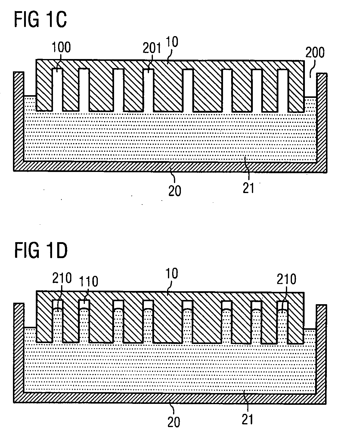
[0027]As shown in FIG. 1B, the transfer board 10 is ready for immersion in a material bath 20 holding a material 21 which is in a liquid state. The material 21 may comprise a metallic or conductive mate...
second embodiment
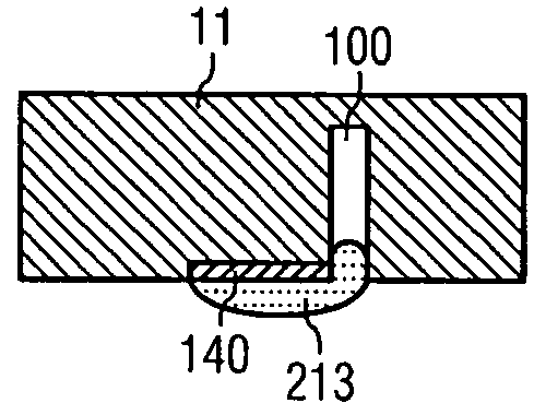
[0034]FIGS. 2A and 2B show the expelling of the material from a transfer board 10 according to the present invention. FIG. 2A shows the transfer board 10 with bevels 101 at a surface of the transfer board 10 in the surrounding of the blind hole openings. If the portion 210 of the material 21 is expelled at least partially form the blind holes 100, pearl-shaped portions 211 of the material 21 may form in the surrounding of the blind hole 100 openings, as shown in FIG. 2B. The essentially curved surface of the pearl-shaped portions 211 allow a punctiform initial mechanical contact when positioned close to a target entity. Starting from this punctiform contact area, contact of the material portion with the target entity, such as a target contact pad, may expand concentrically. In this way, the formation of gas traps and voids is strongly suppressed, and a reliable and uniform joint of the material and the target entity may be obtained. The material 21 may be in a liquid state during th...
third embodiment
[0036]FIGS. 3A and 3B show the expelling of the material from a transfer board 10 according to the present invention. FIG. 3A shows a transfer board with wetting eyes 102 on a surface of the transfer board 10 at the surroundings of the blind hole openings. If the portion 210 of the material 21 is expelled at least partially form the blind holes 10, a pearl-shaped portion 211 of the material 21 may form in the surroundings of the blind hole openings. The wetting eyes 102 may support the formation of the pearl-shaped portions 211 at the transfer board 10. The wetting properties of the wetting eyes 102 may further support an expelling by means of the surface tension and wetting forces of the portion 210 or of pearl-shaped portions 211 of the material 21, as the liquid material 21 may tend to form a droplet. The wetting eyes 102 also may keep the material portions 211 at a well-defined position and therefore inhibit a coalescence of neighboring portions 211. Furthermore, a combination o...
PUM
| Property | Measurement | Unit |
|---|---|---|
| Pressure | aaaaa | aaaaa |
| Pressure | aaaaa | aaaaa |
| Pressure | aaaaa | aaaaa |
Abstract
Description
Claims
Application Information
 - Generate Ideas
- Intellectual Property
- Life Sciences
- Materials
- Tech Scout
- Unparalleled Data Quality
- Higher Quality Content
- 60% Fewer Hallucinations
Browse by: Latest US Patents, China's latest patents, Technical Efficacy Thesaurus, Application Domain, Technology Topic, Popular Technical Reports.
© 2025 PatSnap. All rights reserved.Legal|Privacy policy|Modern Slavery Act Transparency Statement|Sitemap|About US| Contact US: help@patsnap.com