
Permanent magnetic synchronous electrical motor

a permanent magnetic synchronous and electrical motor technology, applied in the direction of dynamo-electric machines, magnetic circuit rotating parts, magnetic circuit shapes/forms/construction, etc., can solve the problems of large torque ripple and inability to effectively reduce torque ripple, and achieve the effect of reducing torque rippl

Inactive Publication Date: 2008-02-07
FANUC LTD
View PDF3 Cites 10 Cited by
  • Summary
  • Abstract
  • Description
  • Claims
  • Application Information

AI Technical Summary

Benefits of technology

[0009] Taking the significance of the shape of the rotor core in the vicinity of the permanent magnet into consideration, an object of the present invention is to provide a permanent magnetic synchronous electrical motor, in which the waveform of the induced voltage is more similar to the sine curve than the prior art, so as to reduce the torque ripple.

Problems solved by technology

However, in such an electric motor, the torque ripple may easily be large.
As a result, the difference between the waveform of the back electromotive force and the sine curve becomes larger, whereby the torque ripple cannot be effectively lowered.

Method used


Image

  • Permanent magnetic synchronous electrical motor
  • Permanent magnetic synchronous electrical motor
  • Permanent magnetic synchronous electrical motor

Examples


Embodiment Construction

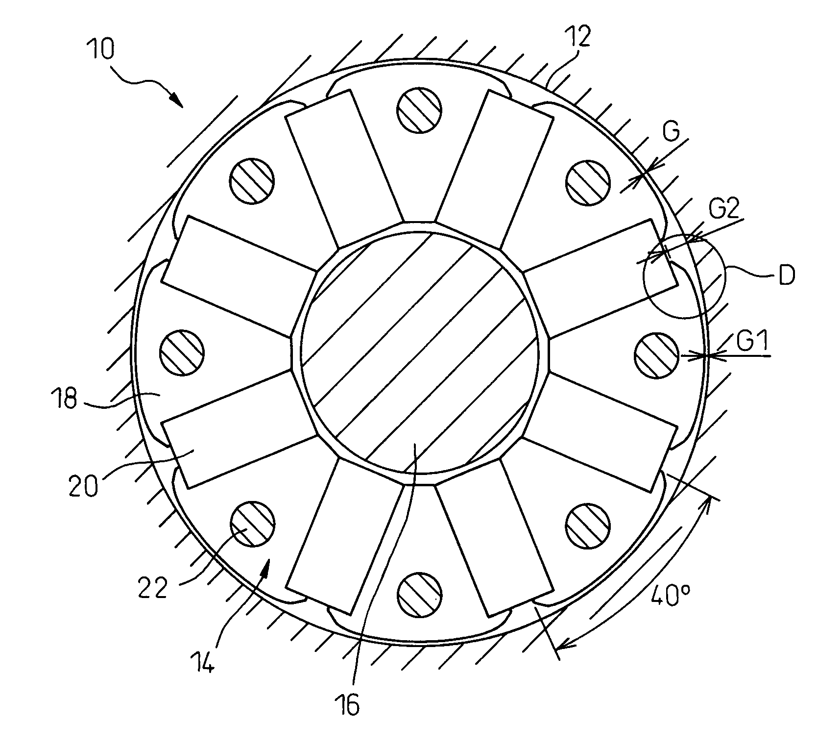
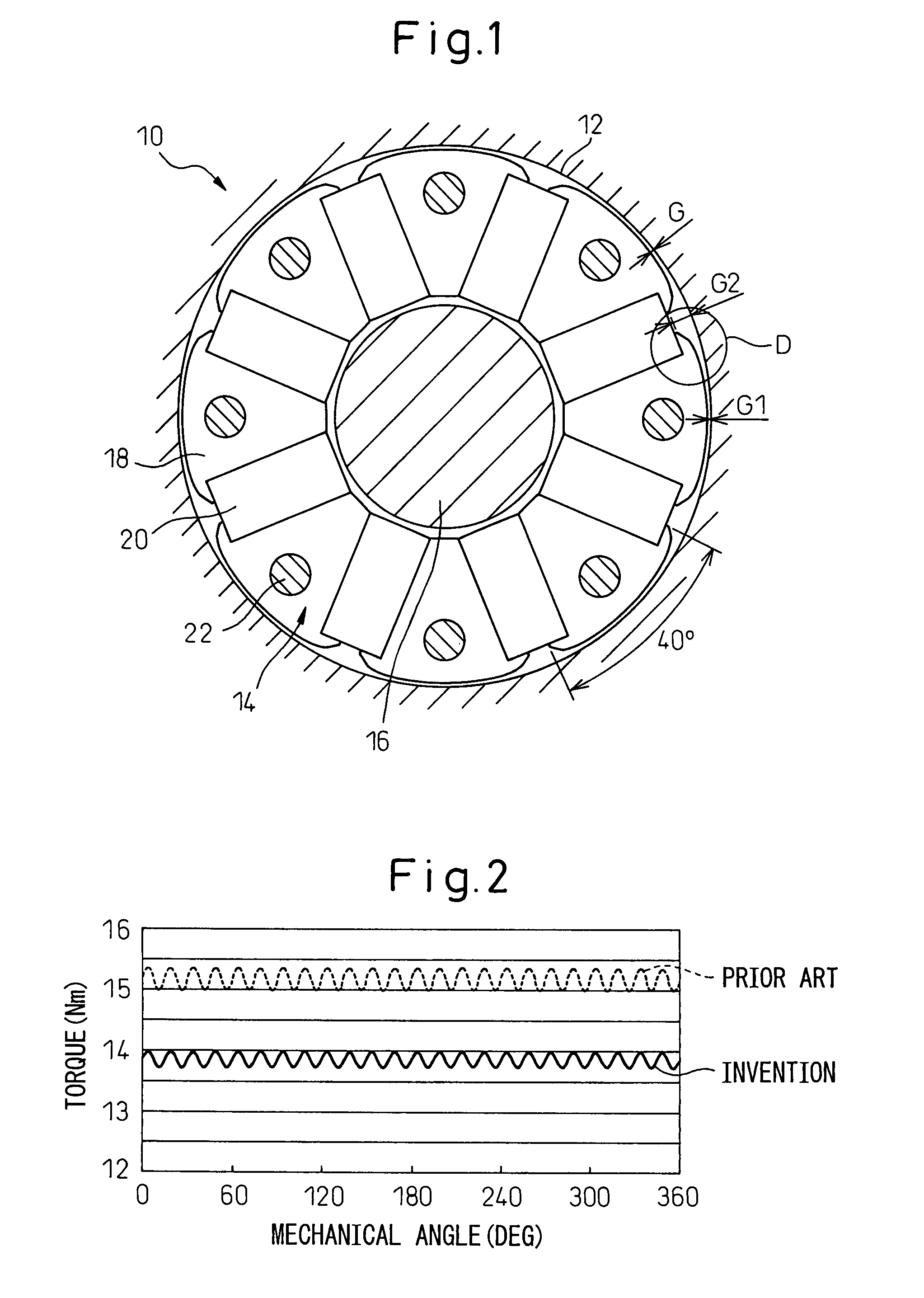
[0021] The invention will be described below with reference to the drawings. As shown in FIG. 1, a permanent magnetic synchronous electrical motor 10 according to a first embodiment of the invention has a stator 12 having an armature winding (not shown), and a rotor 14 spaced by a gap G from the stator 12, and rotatably about a rotation axis 16. In FIG. 1, the stator 12 is shown by roughly indicating only the inner surface thereof. The rotor 14 has a rotor core 18 connected to the rotation axis 16, and a plurality of permanent magnets 20 fixed at equal spaces along the circumferential direction of the rotor core 18. The illustrated rotor core 18 is a so-called eight-pole type rotor core (or having four pairs of poles). In other words, eight permanent magnets are positioned at 45 degrees from each other. When the rotor core 18 is connected to the rotation axis 16, first, an end plate (not shown) is arranged on each axial end of the laminated rotor core 18 and connected to the rotatio...


PUM


Abstract

A permanent magnetic synchronous electrical motor, in which the waveform of the induced voltage is more similar to the sine curve than the prior art, so as to reduce the torque ripple. The outer shape of a rotor core of the electrical motor is specified by using the reciprocal of the cosine function. In the invention, the range of an electrical angle of the rotor, in which the reciprocal of the cosine function is applied to the outer shape of the rotor core, is equal to or more than 160 degrees.

Description

RELATED APPLICATIONS [0001] The present application claims priority from Japanese Patent Application No. 2006-196815, filed on Jul. 19, 2006, the entire contents of which are fully incorporated herein by reference. BACKGROUND OF THE INVENTION [0002] 1. Field of the Invention [0003] The present invention relates to a permanent magnetic synchronous electrical motor, in particular, an electric motor including a rotor core having a shape, to which a reciprocal of a cosine function is applied. [0004] 2. Description of the Related Art [0005] In a permanent magnetic synchronous electrical motor of the prior art, the shape of the rotor core of the motor is basically cylindrical, and has some projections or projecting polarized portions arranged on the outer periphery of the rotor core at equal spaces. In the motor having such a rotor core, torque ripple is relatively large due to the waveform turbulence of a back electromotive force. In recent years, when the waveform of the back electromot...

Claims


Application Information

Patent Timeline
Patent Type & Authority Applications(United States)
IPC IPC(8): H02K21/14H02K1/27
CPCH02K1/2773H02K1/276
Inventor MAEDA, TAKUYAYAMAMOTO, TOMONAGAUEMATSU, HIDETOSHI
Owner FANUC LTD
Learn More