

Image display apparatus
a technology of image display and display screen, which is applied in the field of image display screen, can solve the problems of undesired image processing and undesired image quality change, and achieve the effect of reducing the number of images
- Summary
- Abstract
- Description
- Claims
- Application Information
AI Technical Summary
Benefits of technology
Problems solved by technology
Method used
Image

Examples
first preferred embodiment
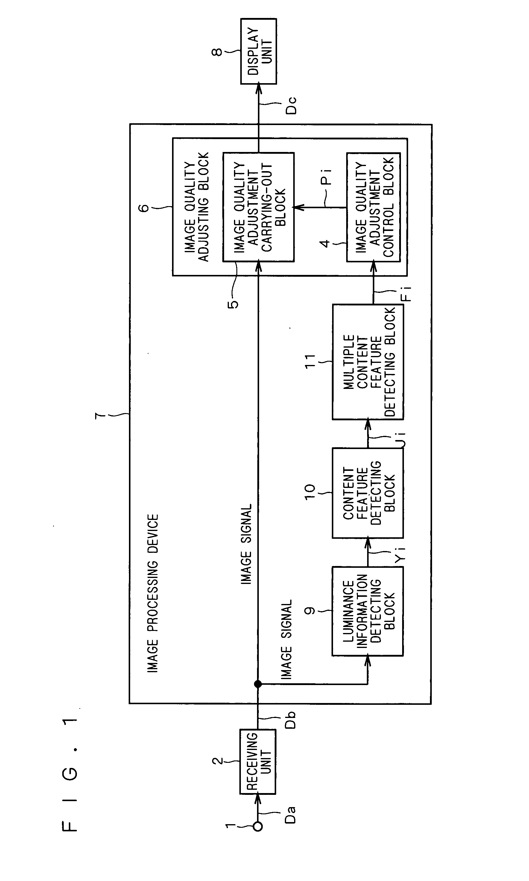
[0045]FIG. 1 is a block diagram illustrating the configuration of an image display apparatus according to a first preferred embodiment of the present invention. The image display apparatus of the first preferred embodiment includes an input terminal 1, a receiving unit 2, an image processing device 7, and a display unit 8. The input terminal 1 receives input of an image signal Da of a given format adapted for television, computers, etc. The receiving unit 2 receives the image signal Da inputted to the input terminal 1, and converts the image signal Da into a format that can be processed in the image processing device 7, and outputs it as an image signal Db. For example, the receiving unit 2 converts the image signal Da into some digital image signals including a luminance signal Y, and outputs them as the image signal Db. For example, when the input image signal Da is an analog signal, the receiving unit 2 includes an A / D converter, and when the input image signal Da is a digital si...
second preferred embodiment
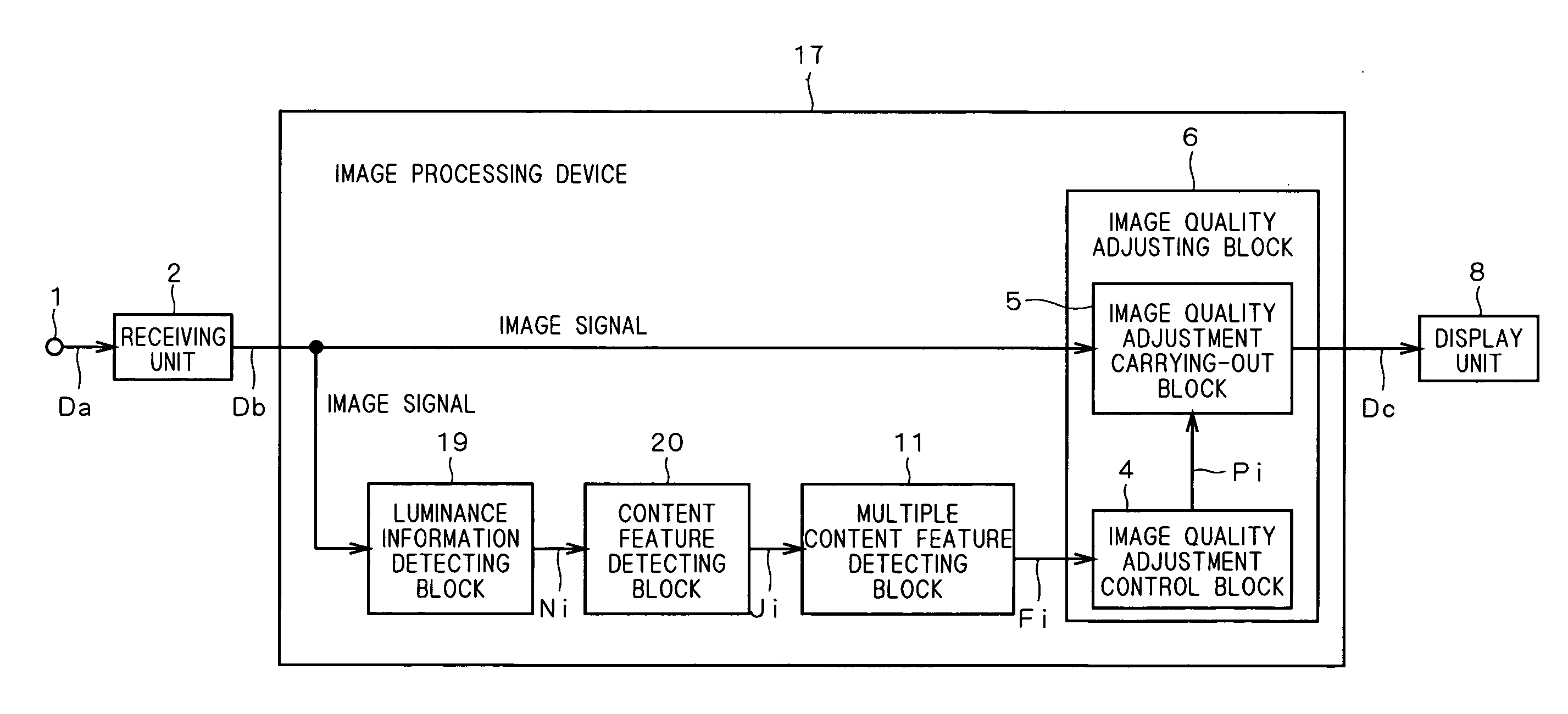
[0104]FIG. 14 is a block diagram illustrating the configuration of an image display apparatus according to a second preferred embodiment of the present invention. The image display apparatus of the second preferred embodiment includes an image processing device 17 in place of the image processing device 7 of the image display apparatus of the first preferred embodiment.
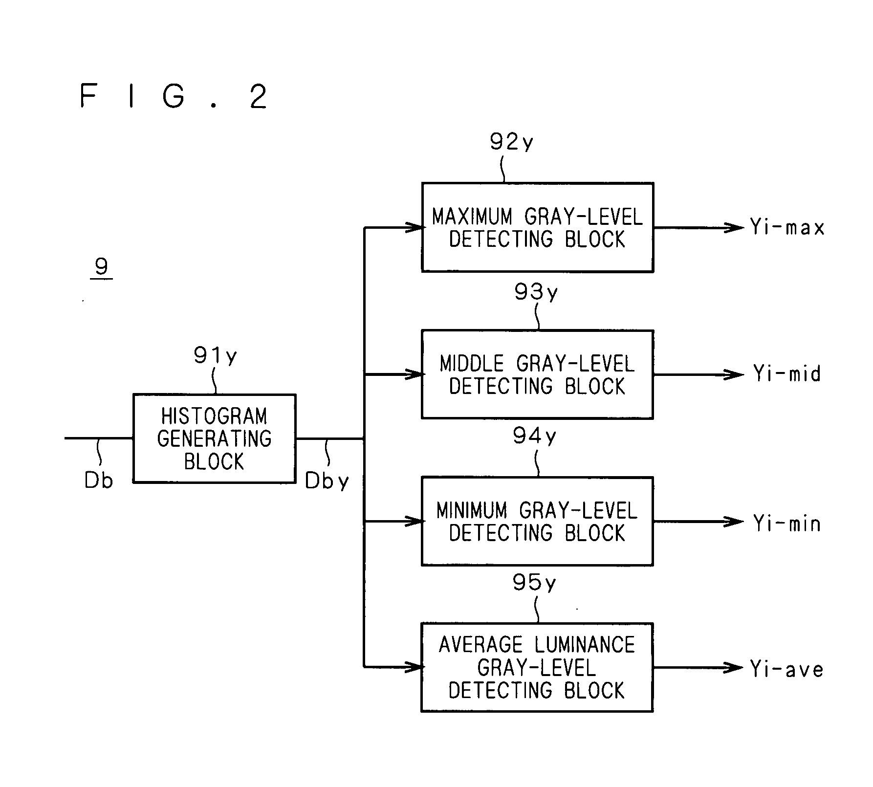
[0105]The image processing device 17 of the second preferred embodiment includes a content feature detecting block 20, a luminance information detecting block 19, a multiple content feature detecting block 11, and the image quality adjusting block 6 of the first preferred embodiment. The luminance information detecting block 19 receives a luminance signal Y contained in an image signal Db outputted from the receiving unit 2, and it detects luminance information about individual pixels from the luminance signal Y, generates a histogram, and outputs a pixel number information value Ni (luminance-related information valu...
third preferred embodiment
[0132]FIG. 22 is a block diagram illustrating the configuration of an image display apparatus according to a third preferred embodiment of the present invention. The image display apparatus of the third preferred embodiment includes an input terminal 1, a receiving unit 2, an image processing device 27, and a display unit 8.
[0133]The input terminal 1 and the receiving unit 2 are the same as those of the first preferred embodiment and so not described here again.
[0134]The image processing device 27 includes a luminance information detecting block 9, a content feature detecting block 10, a multiple content feature detecting block 11, an image quality adjustment carrying-out block 5, an image quality adjustment control block 4, a frame buffer 40, and a scene change detecting block 12. An image signal Db outputted from the receiving unit 2 is inputted to the luminance information detecting block 9 and also to the frame buffer 40 of the video display device 3.
[0135]The luminance informat...
PUM
 Abstract
Description
Claims
Application Information