Image display apparatus and image display method
a technology of image display and image, which is applied in the field of light control technique, can solve the problems that the hue fidelity of a projected image has not been considered in the prior art technique, and achieve the effect of enhancing the hue fidelity of image display
- Summary
- Abstract
- Description
- Claims
- Application Information
AI Technical Summary
Benefits of technology
Problems solved by technology
Method used
Image

Examples
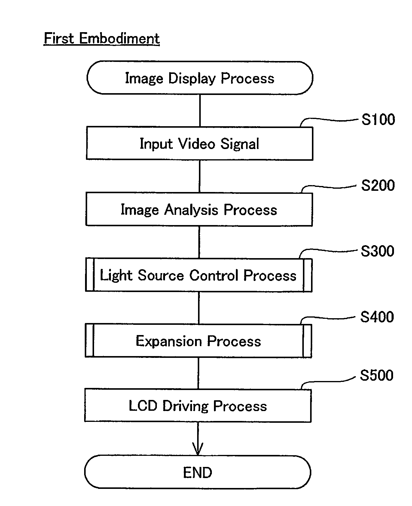
first embodiment
[0026]B. Light Source Control and Light Modulation Processing in First Embodiment
second embodiment
[0027]C. Light Source Control and Light Modulation Processing in Second Embodiment
[0028]D. Modifications
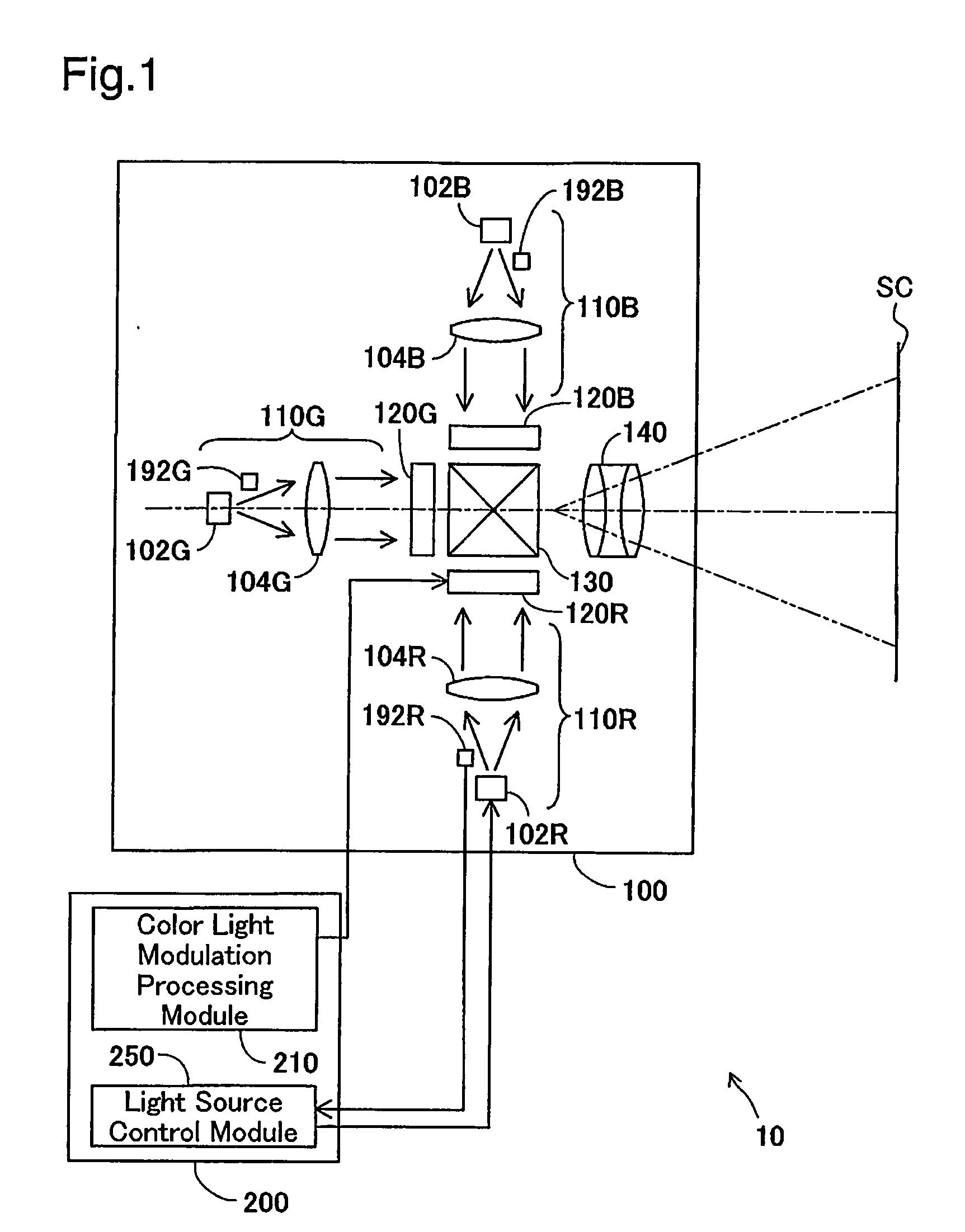
[0029]A. Fundamental Structure of Liquid Crystal Projector
[0030]FIG. 1 is a block diagram schematically illustrating the structure of a liquid crystal projector 10 in one embodiment of the invention. The liquid crystal projector 10 has an optical system 100 to project images on a screen SC and a controller 200 to control projected light. The optical system 100 includes three illumination optical systems 110R, 110G, and 110B that respectively emit color lights of three colors R, G, and B, three liquid crystal light valves 120R, 120G, and 120B that respectively modulate the three emitted color lights, a cross dichroic prism 130 that combines the three modulated color lights to composite light, and a projection lens system 140 that projects the composite light onto the screen SC.
[0031]The illumination optical systems 110R, 110G, and 110B respectively have light emission units 102R, 1...
PUM
 Abstract
Description
Claims
Application Information
PatSnap Eureka turns technology decisions into work you can execute. Powered by our Innovation Knowledge Graph, it runs expert workflows across engineering, life sciences, materials and intellectual property. Get your review-ready output in minutes.


