Exposure Apparatus, Producing Method of Exposure Apparatus, and Producing Method of Microdevice

a technology of exposure apparatus and producing method, which is applied in the direction of photomechanical treatment, printing, instruments, etc., can solve the problem of limited size of exposure apparatus having such pedestals, and achieve the effect of excellent micro-devices

Active Publication Date: 2008-02-07
NIKON CORP
View PDF26 Cites 166 Cited by
  • Summary
  • Abstract
  • Description
  • Claims
  • Application Information

AI Technical Summary

Benefits of technology

[0015] According to the producing method of the exposure apparatus of the invention, the plurality of intermediate pedestals are disposed on the lower pedestal on which the substrate stage is mounted, and the upper pedestal on which at least a portion of the exposure body including the projection optical system is disposed on the plurality of intermediate pedestals. Therefore, it is possible to produce an exposure apparatus capable of exposing onto a large photosensitive substrate using the plurality of pedestals having such size that the pedestals can be transported.
[0016] According to the producing method of the microdevice of the invention, the microdevice is produced using the exposure apparatus of the invention or an exposure apparatus produced using the producing method of the invention. Therefore, it is possible to precisely expose a mask onto a large photosensitive substrate, and an excellent microdevice can be obtained.

Problems solved by technology

However, the size of the exposure apparatus having such pedestals is limited due to width of roads when the exposure apparatus is transported.

Method used


Image

  • Exposure Apparatus, Producing Method of Exposure Apparatus, and Producing Method of Microdevice
  • Exposure Apparatus, Producing Method of Exposure Apparatus, and Producing Method of Microdevice
  • Exposure Apparatus, Producing Method of Exposure Apparatus, and Producing Method of Microdevice

Examples


Embodiment Construction

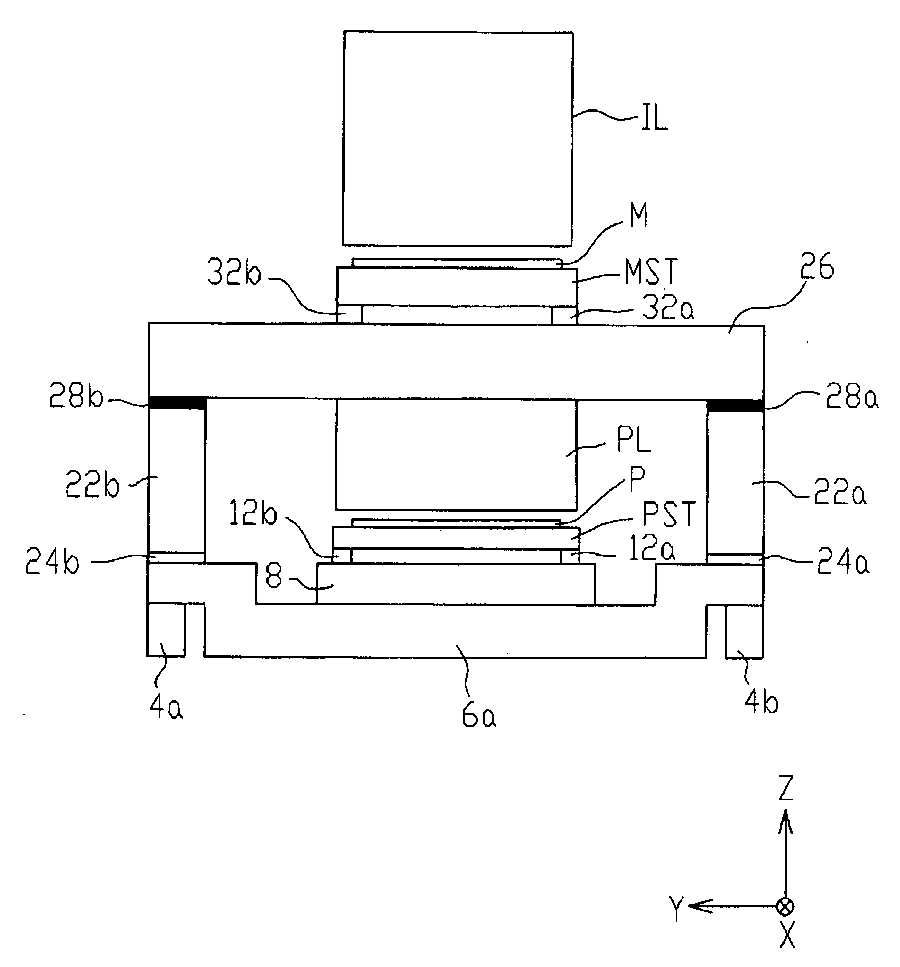
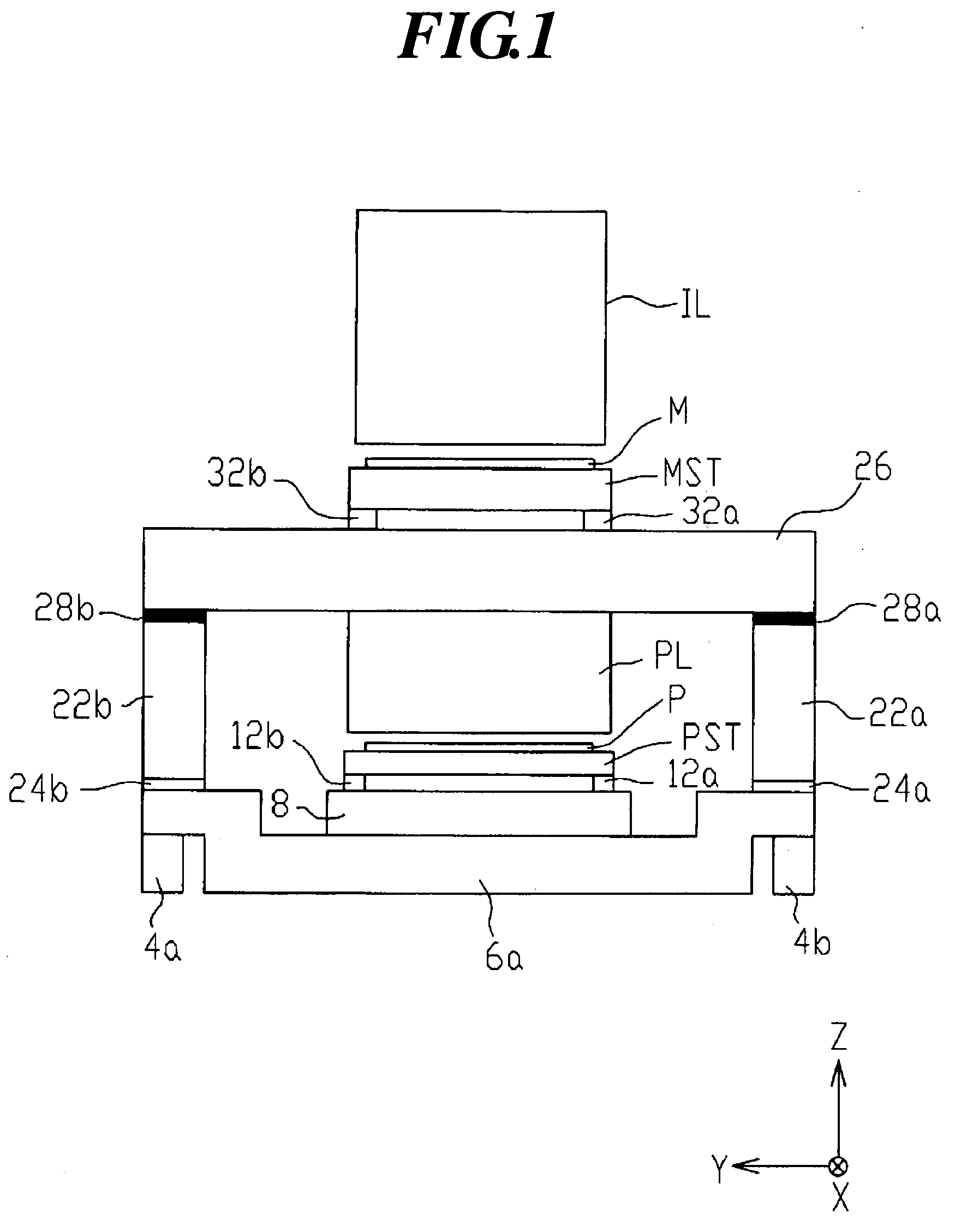
[0024] An exposure apparatus according to an embodiment of the present invention will be explained with reference to the drawings. FIG. 1 is a schematic diagram showing a structure of the exposure apparatus of the embodiment. In the following description, an XYZ rectangular coordinate system shown in FIG. 1 is set, and a positional relationship of various members will be explained with reference to the XYZ rectangular coordinate system. In the XYZ rectangular coordinate system, an X-axis and a Y-axis are in parallel to a plate P, and a Z-axis is perpendicular to the plate P. The XYZ coordinate system in the drawing, an X-Y plane is in parallel to a horizontal plane, and the Z-axis is oriented in the vertical direction. In this embodiment, a direction (scanning direction) in which the plate P (plate stage PST) is moved is in the X-axis direction.

[0025] As shown in FIG. 1, the exposure apparatus includes an illumination optical system IL having a light source and an illumination opti...


PUM


Abstract

An exposure apparatus for exposing a pattern formed on a mask (M) onto a photosensitive substrate (P) through a projection optical system (PL), comprising an upper pedestal (26) on which at least one of the projection optical system (PL) and a mask stage (MST) which is to hold the mask (M) is mounted, and a plurality of lower pedestals (6a) which supports the upper pedestal (26) and which has a longitudinal direction in a predetermined direction.

Description

TECHNICAL FIELD [0001] The present invention relates to an exposure apparatus for producing a microdevice such as a flat panel display element like a liquid crystal display element using a lithography step, and to a producing method of the exposure apparatus, and a producing method of a microdevice using the exposure apparatus. BACKGROUND TECHNIQUE [0002] At present, for producing of a liquid crystal display element device and the like, there is used a photolithography technique for transferring a fine pattern formed on a mask onto a photosensitive substrate. In the producing step using the photolithography technique, a mask is placed on a mask stage which moves two dimensionally, and a projection exposure apparatus is used in this photolithography technique. The projection exposure apparatus projects and exposes a pattern formed on the mask onto a photosensitive substrate to which sensitizer is applied. The sensitizer is placed on a substrate stage which two dimensionally moves thr...

Claims


Application Information

Patent Timeline
Patent Type & Authority Applications(United States)
IPC IPC(8): G03B27/42G03B27/58
CPCG03F7/70791G03F7/70975G03F7/70833
Inventor KAWAMURA, SHUJI
Owner NIKON CORP
Why Eureka
Try Eureka